Advertisement
Quick Links
ENGLISH
Quick Installation Guide
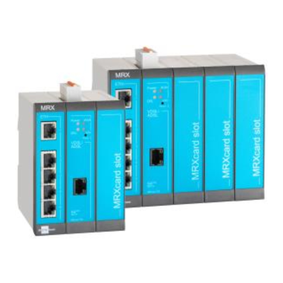
MRX DSL
These short operating instructions apply for the following devices of INSYS icom:
▪ MRX3 DSL
▪ MRX5 DSL
It is intended for a quick commissioning by the operator. Refer to the associated manual for further information.
This and other associated manuals can be found on our website in the menu Support > Documentation and
Downloads. Scan the QR code above or enter the URL into your web browser.
Technical Data
The product is only intended for the use within the permissible technical limits specified in the data sheets. These limits m ust be observed.
Operating voltage (redundant)
Power consumption
Level input IN1
Current consumption input IN1
at LOW potential
Level input IN2
Current consumption input IN2
at HIGH potential
A
Only for MRX3/5 DSL-A
B
Only for MRX3/5 DSL-B
Technical Boundaries
Max. line length for antennas, power supplies, serial interfaces, inputs and outputs as well as other signals: 30 m
Max. line length of USB connection lines: 3 m
Cable cross-section: 0.25 ... 1.5 (2.5) mm² (depending on terminal size), flexible lines require end sleeves
A splitter must be connected upstream when connecting to DSL lines in telephone networks like Annex A or Annex B.
Support
If you need further support, please contact your sales partner or INSYS icom support. You can contact our support department via e-mail
under support@insys-icom.de.
Defects Liability Terms
A use other than the intended use, an ignorance of the safety instructions and the documentation, the use of insufficiently q ualified
personnel as well as unauthorised modifications exclude the liability of the manufacturer for damages resu lting from this. The liability of the
manufacturer ceases to exist.
In tended Use
The product may only be used for the purposes specified in the function overview of the manual. In addition, it may be used f or the
following purposes:
▪ Usage and mounting in an industrial cabinet.
▪ Switching and data transmission functions in machines according to the machine directive 2006/42/EC.
▪ Usage as data transmission device, e.g. for a PLC.
The product may n ot be used for the following purposes and used or operated under the following conditions:
▪ Use, control, switching and data transmission in machines or systems in explosive atmospheres.
▪ Controlling, switching and data transmission of machines, which may involve risks to life and limb due to their functions or when a
breakdown occurs.
12 V ... 24 V DC (±20%)
approx. 6 W
fully equipped: max. 20 W
HIGH level = 2 ... 24 V
LOW level = 0 ... 1 V
Contact open condition: HIGH
typ. 0.1 mA when connecting to
GND
HIGH level = 10 ... 24 V
LOW level = 0 ... 5 V
Contact open condition: LOW
max. 3 mA at 24 V DC
www.insys-icom.com/manual
Supported DSL standards
A
Supported DSL standards
B
Supported DSL standards
Real-time clock (RTC) buffer
time
Temperature range
Maximum permissible
humidity
IP rating
VDSL2 G.993.2 Profile 8a, 8b,
8c, 8d, 12a, 12b, 17a. 30a
VDSL2 Vectoring G.993.5
ADSL G.992.1 Annex A,
G.992.3. Annex A/L/M, G.992.5
Annex A and M, T1.413
ADSL G.992.1 Annex B,
G.992.3. Annex B, G.992.5
Annex B and J
typ. 2 days
0 °C ... 50 °C
(-25 °C ... 55 °C extended)
95% non-condensing
Housing IP40
www.insys-icom.com
Advertisement

Related Manuals for insys icom MRX DSL


Summary of Contents for insys icom MRX DSL
- Page 1 A splitter must be connected upstream when connecting to DSL lines in telephone networks like Annex A or Annex B. Support If you need further support, please contact your sales partner or INSYS icom support. You can contact our support department via e-mail under support@insys-icom.de.
- Page 2 ENGLISH Quick Installation Guide MRX DSL Router connection Connect DSL connection line with VDSL/ADSL socket Connect supply voltage (12 V … 24 V DC (±20%)) to the terminals V+ and GND Connect router (ETH 1) to the configuration PC Connect router (ETH 2) to the network...
- Page 3 ENGLISH Quick Installation Guide MRX DSL Configuration as DSL router In Menu Help > Wizards: Select Startup Wizard Select Internet access via DSL (refer to inline help for WAN over Ethernet) These data can be found in the contract documents or can be requested from the provider.
- Page 4 ENGLISH Quick Installation Guide MRX DSL IP address in configuration network The IP address of the router in the configuration network does only have to be changed, if the IP address is already used or a different address range is required. Then, the web interface is immediately accessible under the new address.
Need help?
Do you have a question about the MRX DSL and is the answer not in the manual?
Questions and answers