Table of Contents
Advertisement
Quick Links
Advertisement
Table of Contents

Related Manuals for insys icom SCR Series


Summary of Contents for insys icom SCR Series
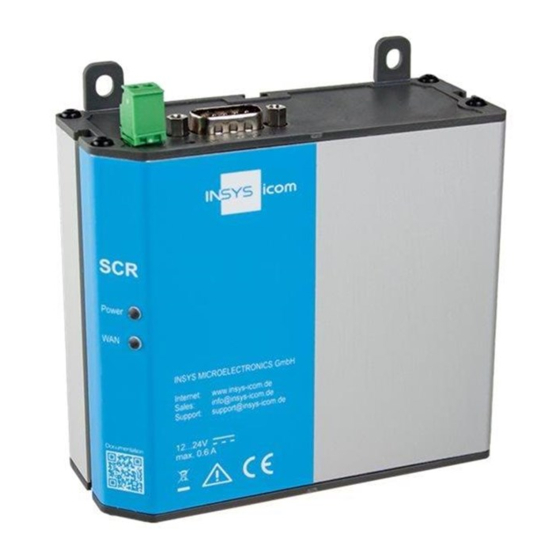
- Page 1 Installation and User Manual...
- Page 3 Copyright © January 2022 INSYS MICROELECTRONICS GmbH Any duplication of this manual is prohibited. All rights on this documentation and the devices are with INSYS MICROELECTRONICS GmbH Regensburg. Trademarks The use of a trademark not shown below is not an indication that it is freely availa- ble for use.
-
Page 4: Table Of Contents
Content Preface ....................6 Defects Liability Terms ..................6 Applicability ......................6 Feedback ......................6 Marking of Warnings and Notes ................7 Symbols and the Formatting in this Manual ............8 Safety Instructions ................. 9 Intended Use ....................... 9 Permissible Technical Limits................10 Responsibilities of the Operator ................. - Page 5 Contents Assembly ..................... 31 DIN rail mounting ....................32 Mounting the DIN rail adapter ................34 Screw mounting ....................36 Connecting the power supply ................37 Commissioning ..................38 Operating Principle ................41 11.1 Operation via the web interface ................. 41 11.2 Authentication to the Router ................
-
Page 6: Preface
We are looking forward to any of your feed- back. Please send an e-mail to support@insys-icom.de. We'd like to know your applications. Please send us a few headwords that we know the applications you solve using products of INSYS icom. -
Page 7: Marking Of Warnings And Notes
Preface Marking of Warnings and Notes Symbols and Key Words Danger! Risk of severe or fatal injury One of these symbols in conjunction with the key word Danger indicates an imminent danger. It will cause death or severe injuries if not avoided. Warning! Personal injury This symbol in conjunction with the key word Warning... -
Page 8: Symbols And The Formatting In This Manual
Preface Symbols and the Formatting in this Manual This section describes the definition, formatting and symbols used in this manual. The various symbols are meant to help you read and find the information relevant to you. The following text is structured like a typical operating instruction of this manual. -
Page 9: Safety Instructions
Safety Instructions Safety Instructions The Safety Instruction section provides an overview about the safety instructions, which must be observed for the operation of the product. The product is constructed according to the currently valid state-of-the-art technol- ogy and reliable in operation. It has been checked and left the factory in flawless condition concerning safety. -
Page 10: Permissible Technical Limits
Safety Instructions Permissible Technical Limits The product is only intended for the use within the permissible technical limits specified in the data sheets. The following permissible limits must be observed: The ambient temperature limits must not be fallen below or exceeded. -
Page 11: Markings On The Product
Safety Instructions Markings on the Product The identification plate of the product is either a print or a label on a face of the product. Amongst other things, it can contain the following markings, which are explained in detail here. Observe manual This symbol indicates that the manual of the product contains essential safety instructions that must be followed implicitly. -
Page 12: Safety Instructions For Electrical Installation
Safety Instructions Safety Instructions for Electrical Installation The electrical connection must only be made by authorised expert personnel ac- cording to the wiring diagrams. The notes to the electrical connection in the manual must be observed. Otherwise, the protection category might be affected. The safe disconnection of circuits, which are hazardous when touched, is only en- sured if the connected devices meet the requirements of VDE T.101 (Basic require- ments for safe disconnection). -
Page 13: General Safety Instructions
Safety Instructions General Safety Instructions Caution! Electrostatic discharges may damage the product! Damage of the product. Observe the general safety precautions when handling electrostatic-discharge-sensitive parts. Caution! Incomplete voltage isolation! Damage of the product. To isolate the voltage from the device, disconnect any supply circuit with its respective isolation device if a redundant power supply is used. - Page 14 Safety Instructions Caution! Short circuits and damage due to improper repairs and modifications as well as opening of maintenance areas! Fire hazard and damage of the product. It is not permitted to open the product for repair or modification exceeding the removal or installation of the designated plug-in cards.
-
Page 15: Security
IT Security IT Security Note Insecure configured router may compromise applications relevant to security! Follow the information in our IT Security Guide for protecting your router: https://docs.insys-icom.de/itsec/en_itsec_guide.html You will find there a Secure Configuration Guide (https://docs.insys- icom.de/itsec/en_itsec_secure_config_guide.html) for a configuration that complies with the accelerated security certification of the German Federal Office for Information Security (BSI). -
Page 16: Using Open Source Software
Using Open Source Software Using Open Source Software General Information This product contains, amongst others, so-called open-source software that is pro- vided by third parties and has been published for free public use. The open-source software is subject to special open-source software licenses and the copyright of third parties. -
Page 17: Special Liability Regulations
Using Open Source Software Special Liability Regulations We do not assume any warranty or liability, if the open-source software programs contained in our product are used by the customer in a manner that does not com- ply any more with the purpose of the contract, which is the basis of the acquisition of our product. -
Page 18: Version History
Version History Version History Version Modification Release New behaviour of the Power LED with icom OS 3.2 DIN rail adapter in scope of delivery Dimensional drawing added Mounting revised, notes regarding cellular variants Update for firmware 4.4 Addition of IT Security note with link to guide Update of notes regarding the extended temperature range Addition of MTBF to Technical Data Update of safety notes... -
Page 19: Device Variants
Device Variants Device Variants This manual describes different variants of the industrial router series SCR of INSYS icom. The routers are referred to as SCR in the manual. The routers are: • SCR-E200 (LAN-LAN router without I/Os) • SCR-E300 (LAN-LAN router with I/Os) •... -
Page 20: Scope Of Delivery
• Safety Instructions • DIN rail adapter The scope of delivery does not include optional accessories. Among other things, the following parts are available from your distributor or INSYS icom: • Cellular antennas • Antenna extensions • Din rail power supply units •... -
Page 21: Technical Information
Technical Information Technical Information The following information applies to all variants of the router. If these variants dif- fer, the different values will be indicated separately. Technical Data 8.1.1 Physical Features All specified data was measured with nominal input voltage, at full load, and an ambient temperature of 25 ℃. - Page 22 Technical Information Physical Feature Value IP rating Housing IP40 Environmental conditions Vibration/shock as per PLC standard EN 61131-2 and EN 60068-2-6, EN 60068-2-27 Temperature tests as per EN 60068- 2-1, EN 60068-2-2, EN 60068-2-14, EN 60068-2-30 MTBF > 770.000 h (25 °C), as per standard SN 29500 (as per IEC 61709) Table 1: SCR –...
-
Page 23: 8.1.2 Technological Features
Technical Information 8.1.2 Technological Features Technological Feature Description Ethernet port 10/100 Mbit/s full/half duplex auto sense; automatic detection of "crossover" or "patch" wiring. RS232 interface Max. baud rate 230,400 bit/s; hardware handshake RTS/CTS; software handshake XON/XOFF; various data formats LTE frequency bands 1 (2100), 3 (1800), 8 (900), 20 (800, 28 (700) (4G) LTE Cat. - Page 24 Technical Information Connector Description V- V+ Power supply Reset Reset key RS232 Serial RS232 interface (D-Sub connector, V.28) SIM card reader (only SCR-L) Cellular antenna (SMA socket, only SCR-L) I/O interface 1 (only SCR-E/L300) Table 3: SCR – connections, display and control elements at the top ...
- Page 25 Technical Information Figure 3: SCR – connections, display and control elements at the front...
- Page 26 Technical Information Colour Function blinking 1x during soft reset Power green Supply 3x during reset to present available default settings green WAN chain inactive establishing established no signal logged in (field Signal Signal green or logged strength see Table (only SCR-L) Link / green Data traffic...
-
Page 27: Power Supply
Technical Information Power supply The connection to an AC supply network must be made using a suitable power supply unit. Figure 4: SCR – power supply connection Connector Description Power supply, negative terminal Power supply, positive terminal Table 8: SCR – power supply connections Inputs and Outputs Figure 5: SCR –... -
Page 28: 8.4.2 Digital Outputs
Technical Information Figure 6: SCR – Digital inputs – connection example 8.4.2 Digital outputs The router has two digital outputs that are designed as open collector outputs. You'll find more information in Table 1. The figure below shows two examples for the connection of the output, the connection of a relay on the left and the connec- tion of an LED on the right. -
Page 29: Rs232 Interface
Technical Information RS232 interface Figure 8: SCR – RS232 interface connection Connector Signal Description Data Carrier Detect Receive Data Transmit Data Data Terminal Ready Ground Data Set Ready Request To Send Clear To Send Ring Indication Table 10: SCR – RS232 interface connection ... -
Page 30: Approvals
Technical Information Approvals The router has the following approvals: • EMC, transient emissions: EN 61000-6-3, EN 55032 Class B • EMC, immunity to interference: EN 61000-6-2, EN 55024 • Product safety: IEC/EN 62368-1 • CE (MRO-L200) • FCC Part 15 Class B, IC (MRO-L210) -
Page 31: Assembly
Assembly Assembly The router can be mounted in two different ways: • DIN rail mounting using the optional DIN rail adapter • Screw mounting using the four mounting lugs This section describes how you can install the router, connect the power supply and demount it again. -
Page 32: Din Rail Mounting
Assembly Figure 9: SCR – Dimensions DIN rail mounting A DIN rail adapter is attached for DIN rail mounting. Depending on the batch, the adapter is made of aluminium (silver) or plastic (black). The two versions differ somewhat in handling and are described separately below. Depending on the space available in the switch cabinet, the adapter may be in- serted into the groove at the back or at the side (more space in width or depth). - Page 33 Assembly Figure 11: SCR – DIN rail mounting The router is now readily mounted. Removing the device from the DIN rail How to uninstall the router from a DIN rail in a switch cabinet: The power supply of the switch cabinet is switched off and secured against being switched on accidentally.
-
Page 34: 9.2 Mounting The Din Rail Adapter
Assembly Plastic adapter shown, aluminium adapter must be pressed downwards. Figure 12: SCR – DIN rail removal The router is now removed. 9.2 Mounting the DIN rail adapter The DIN rail adapter is mounted to the narrower side of the router when delivered, but can be relocated depending on the requirements to the mounting location. - Page 35 Assembly The retaining spring is now pretensioned for mounting. Figure 13: DIN rail mounting – pretensioning the accessory adapter Mounting the adapter to the housing How to mount the DIN rail adapter to the router housing: Hold the adapter in a way that the retaining spring remains pretensioned and place it on the housing so that you can slide the square nuts at the screws into the housing groove.
-
Page 36: Screw Mounting
Assembly Screw mounting The four mounting lugs provided at the housing allow mounting on even and stable underground. The mounting material is not included and must be selected accord- ing to the underground. Mounting the device using screws How to mount the router to an even underground: ... -
Page 37: Connecting The Power Supply
Assembly Drill the four mounting bores using a suitable drill bit in the required diameter into the underground. Screw the router against the underground at all four mounting lugs with a wahser under the screw head. The router is now readily mounted. Connecting the power supply Connecting the power supply ... -
Page 38: Commissioning
Commissioning Commissioning This chapter describes how to commission the router, i.e. how to connect it to a PC and how to prepare it for the configuration. Insert SIM card (only cellular version). How to insert the SIM card. The power supply is disabled. ... - Page 39 How to connect the router to a cellular antenna. The power supply is disabled. You will need a suitable cellular antenna (available from INSYS icom). When selecting and mounting the antenna, make sure to comply with CE conformity.
- Page 40 Commissioning Open a web browser and enter the URL "https://192.168.1.1" into the address bar. The browser loads the start page of the router. ➢ If you see the message in your browser window that the page with this address cannot be found, follow the following steps: Check, whether the device is supplied with power.
-
Page 41: Operating Principle
Operating Principle Operating Principle This chapter describes how to operate and configure the router. There are different options for configuration and operation: • Via a web-based interface (web interface). The web interface itself is displayed and operated using a web browser. Operation via web interface and access via HTTPS protocol are described in the following. - Page 42 Operating Principle The device is ready for operation and you have access to it (refer to Commissioning section). Start the web browser and enter the IP address into the address bar. The factory default IP address is 192.168.1.1. Access is only possible via HTTPS in default settings.
-
Page 43: Authentication To The Router
Operating Principle 11.2 Authentication to the Router No authentication is configured in default settings. Access to the web interface is possible without login. Changes can be made. However, the changes can only be activated, after an authentication has been configured. Available authentication methods are: •... -
Page 44: Access Via Https Protocol
Operating Principle 11.3 Access via HTTPS Protocol The web interface only allows secure configuration using the HTTPS protocol in default settings. The HTTPS protocol allows an authentication of the server (i.e. the router) as well as an encryption of the data transmission. It is not recommended to enable access via the HTTP protocol. -
Page 45: Authentication Via An Own Certificate Structure
Operating Principle 11.3.2 Authentication via an own certificate structure A more secure alternative is to use your own certificate structure and load a self-generated certificate/key combination onto the router and then use this for access via an HTTPS connection. Proceed as follows in coordination with the IT security department of your company to ensure a secure availability of the router: 1. -
Page 46: Profiles And Profile Handling
Operating Principle 11.4 Profiles and Profile Handling The configuration of the router is called profile. Several profiles can be stored on one device so that the configuration of a device can be changed quickly. 11.4.1 Term definitions The following terms or conditions are to be distinguished for profiles: •... -
Page 47: Using Several Profiles
Operating Principle 11.4.3 Using several profiles The versatile possible applications of the router suggest the use of several profiles. The following sections describe the profile handling. 11.4.3.1 Storing a profile Settings made in the opened profile are stored in this profile with a click on the but- ton "OK". -
Page 48: Ascii Configuration
Operating Principle 11.4.3.6 Importing a profile Profiles (in binary format) or ASCII configuration files can be uploaded to the router in the "Administration" menu on the Profiles" page. “ You need to locate the respective file on the computer under "Import profile or ASCII configuration file"... -
Page 49: Maintenance, Troubleshooting And Repair
If a failure occurs during the operation of the product, you will find troubleshooting tips on our support page (https://www.insys-icom.com/en/help/). If you need fur- ther support, please contact your reseller or INSYS icom. You can contact our sup- port team via e-mail under support@insys-icom.de. -
Page 50: Waste Disposal
Waste Disposal Waste Disposal 13.1 Repurchasing of Legacy Systems According to the new WEEE guidelines, the repurchasing and recycling of legacy systems for our clients is regulated as follows: Please send those legacy systems to the following address, carriage prepaid: Frankenberg-Metalle Gaertnersleite 8 D-96450 Coburg... -
Page 51: Declaration Of Conformity
Declaration of Conformity Declaration of Conformity 14.1 Devices with radio technology Hereby, INSYS Microelectronics GmbH declares that the device type SCR-L is in compliance with Directives 2014/53/EU and 2011/65/EU. The full text of the EC Declaration of Conformity is available under the following Internet address: www.insys-icom.com/manual For compliance with CE conformity, it is also necessary to comply with DIN EN62311. -
Page 52: Fcc Statement
FCC Statement FCC Statement Note: Certain variants of this device comply with part 15 of the FCC Rules (this is indicated by the FCC symbol on the label). Operation is subject to the following two conditions: (1) This device may not cause harmful interference, and (2) this device must accept any interference received, including interference that may cause unde- sired operation. -
Page 53: Export Restriction
Export Restriction Export Restriction The chip sets for analogue modems and cellular radio adapters used by INSYS Mi- croelectronics GmbH are subject to export restrictions as per US ECCN classifica- tion (5A991). Therefore, it is not allowed to export these communication devices into the follow- ing countries (at the time when this publication has been issued): Cuba, Iran, North Korea, Sudan, Syria The currently effective country list can be found in section „Country Group E“... -
Page 54: Glossary
Glossary Glossary This describes the most important terms and abbreviations of this manual. APN: Access Point Name, computer name that provides cellular subscribers of the GPRS network with Internet access. AT command: Commands to devices such as modems to set up this device. Broadcast: Data packet that is sent to all participants of a network. - Page 55 Glossary GSM: Global System for Mobile communications; cellular network for voice and data transmission. ICMP: Internet Control Message Protocol; protocol that is often used to con- trol a network. The program "ping" uses ICMP for example. Interface: A network device that can transport IP connections. IP address: Internet Protocol address;...
- Page 56 Glossary PPP: Point to Point Protocol; a protocol, which connects two machines via a serial line to enable the exchange of TCP/IP packets between those two machines. PPPoE: Point to Point Protocol over Ethernet; a protocol, which connects two devices via an Ethernet line to enable the exchange of TCP/IP packets between those two machines.
- Page 57 Glossary VPN: Virtual Private Network; logical connections (so-called tunnels) are es- tablished via existing unsafe connections. The end points of these con- nections (tunnel ends) and the devices behind can be considered as an independent logical network. A very high degree of tap- and tamper- resistance can be achieved with the encryption of the data transmis- sion via the tunnels and the previous two-way authentication of the partcipants at this logical network.
-
Page 58: Tables And Diagrams
Tables and Diagrams Tables and Diagrams 18.1 List of Tables Table 1: SCR – physical features ................22 Table 2: SCR – technological features ..............23 Table 3: SCR – connections, display and control elements at the top ....24 Table 4: SCR –... -
Page 59: Index
Index Index Access Point Name ......54 General safety instructions ....13 Accessories ........20 GPRS ..........54 Additional information ....... 8 Ground ..........27 Alternative results ......8 GSM ..........55 APN ..........54 Housing ........... 14 Assembly ......... 31 HTTPS .......... - Page 60 Index PAP..........55 Service Center Number ....56 PC ............ 39 Short-cut ........14, 49 Permissible limit ......10 Signal LED ........26 Personnel ........10 SIM card .......... 38 PIN ..........38 SIM card reader ......23, 24 Port ..........55 SMS..........
Need help?
Do you have a question about the SCR Series and is the answer not in the manual?
Questions and answers