Table of Contents
Advertisement
Quick Links
Advertisement
Table of Contents

Related Manuals for HIKVISION HYU-559


Summary of Contents for HIKVISION HYU-559
- Page 1 VIDEO INTERCOM INDOOR STATION (HYU-559) User Manual...
- Page 2 Video Intercom Indoor Station·User Manual User Manual This user manual is intended for users of the indoor station. It includes instructions on how to use the Product. The software embodied in the Product is governed by the user license agreement covering that Product. Disclaimer REGARDING TO THE PRODUCT WITH INTERNET ACCESS, THE USE OF PRODUCT SHALL BE WHOLLY AT YOUR OWN RISKS.
- Page 3 Video Intercom Indoor Station·User Manual Regulatory Information FCC Information Please take attention that changes or modification not expressly approved by the party responsible for compliance could void the user’s authority to operate the equipment. FCC compliance: This equipment has been tested and found to comply with the limits for a Class A digital device, pursuant to part 15 of the FCC Rules.
- Page 4 Video Intercom Indoor Station·User Manual Safety Instruction These instructions are intended to ensure that user can use the product correctly to avoid danger or property loss. The precaution measure is divided into Warnings and Cautions: Warnings: Neglecting any of the warnings may cause serious injury or death. Cautions: Neglecting any of the cautions may cause injury or equipment damage.
- Page 5 Video Intercom Indoor Station·User Manual Exposing the equipment to direct sun light, low ventilation or heat source such as heater or radiator is forbidden (ignorance can cause fire danger). Do not aim the device at the sun or extra bright places. A blooming or smear may occur otherwise (which is not a malfunction however), and affecting the endurance of sensor at the same time.
-
Page 6: Table Of Contents
Video Intercom Indoor Station·User Manual Table of Contents 1 Overview ...................... 1 1.1 Introduction ......................1 1.2 Main Features ......................1 2 Typical Application ..................2 3 Appearance ....................3 3.1 Appearance of 8-Series Indoor Station ..............3 3.2 Appearance of Type I 6-Series Indoor Station ............4 3.3 Appearance of Type II and Type III 6-Series Indoor Station ........ - Page 7 Video Intercom Indoor Station·User Manual 6.5 Sound Settings ....................... 31 6.6 Do Not Disturb Settings ..................32 6.7 Zone Settings ......................33 6.8 Arming Mode Settings ................... 34 6.9 System Maintenance ..................... 35 6.10 Call Settings ......................36 6.10.1 Add Contact ....................36 6.10.2 Call Resident ....................
- Page 8 Video Intercom Indoor Station·User Manual 8.5.3 View Live Video of Door Station and Outer Door Station ....... 88 8.5.4 View Call Logs ....................89 8.5.5 Release Notice ....................89 8.5.6 Search Video Intercom Information ..............91 9 Accessing via HYU-CONNECT APP Client Software ........96 9.1 Install Software ......................
-
Page 9: Overview
Video Intercom Indoor Station·User Manual 1 Overview 1.1 Introduction The video intercom system can realize functions such as video intercom, resident-to-resident video call, live view of HD video, access control, one-card system, elevator linkage, zone alarm, notice information and visitor messages to provide a complete smart community video intercom system. -
Page 10: Typical Application
Video Intercom Indoor Station·User Manual 2 Typical Application Client Software (PC) Wi-Fi/3G/4G Internet Indoor Indoor Wi-Fi Extension 1 Extension 2 Video/Audio Distributor Resident 2 Resident 1... -
Page 11: Appearance
Video Intercom Indoor Station·User Manual 3 Appearance 3.1 Appearance of 8-Series Indoor Station Table 3-1 Components Description Description Built-in Camera Power Supply Indicator Information Indicator Alarm Indicator SOS Touch Key Unlock Touch Key Live View Touch Key Management Center Touch Key LCD Display Screen Microphone Table 3-2 Components Description... -
Page 12: Appearance Of Type I 6-Series Indoor Station
Video Intercom Indoor Station·User Manual 3.2 Appearance of Type I 6-Series Indoor Station Table 3-3 Components Description Description Power Supply Indicator Information Indicator Alarm Indicator SOS Key Unlock Key Live View Key Management Center Key LCD Display Screen Microphone Table 3-4 Components Description Description Power Supply Interface Network Interface... -
Page 13: Appearance Of Type Ii And Type Iii 6-Series Indoor Station
Video Intercom Indoor Station·User Manual 3.3 Appearance of Type II and Type III 6-Series Indoor Station Table 3-5 Components Description Description Power Supply Indicator Information Indicator Alarm Indicator SOS Key Unlock Key Live View Key Management Center Key LCD Display Screen Microphone Table 3-6 Components Description Description... - Page 14 Video Intercom Indoor Station·User Manual Keys Hold Press SOS Key Return Key Direction Keys and /Unlock Key Live View Key Alarm Direction Keys and Management Center Key Confirm Key...
-
Page 15: Terminals And Wiring
Video Intercom Indoor Station·User Manual 4 Terminals and Wiring 4.1 Terminal Description 4.1.1 Terminals and Interfaces of 8-Series Indoor Station Table 4-1 Descriptions of Terminals and Interfaces Name Interface Description RS485B+ RS485B- Communication RS-485 Communication Interfaces RS485A+ Port RS485A- Grounding Grounding Grounding COM1... -
Page 16: Terminals And Interfaces Of Type I 6-Series Indoor Station
Video Intercom Indoor Station·User Manual Name Interface Description JIN3 Zone Detector Input Terminal 3 JIN2 Zone Detector Input Terminal 2 JIN1 Zone Detector Input Terminal 1 4.1.2 Terminals and Interfaces of Type I 6-Series Indoor Station Table 4-2 Descriptions of Terminals and Interfaces Name Interface Description... -
Page 17: Terminals And Interfaces Of Type Ii And Type Iii 6-Series Indoor Station
Video Intercom Indoor Station·User Manual 4.1.3 Terminals and Interfaces of Type II and Type III 6-Series Indoor Station Table 4-3 Terminals Description Name Interface Description AIN1 Zone Detector Input Terminal 1 Terminals AIN2 Zone Detector Input Terminal 2 Grounding 4.2 Wiring Description 4.2.1 Wiring of 8-Series Indoor Station There are 20 pins in the terminal on the rear panel of the indoor station: 4 RS-485 pins, 4 GND pins, 4 alarm output pins, and 8 alarm input pins. -
Page 18: Wiring Of Type I 6-Series Indoor Station
Video Intercom Indoor Station·User Manual Wiring Description (Alarm Output Device) 4.2.2 Wiring of Type I 6-Series Indoor Station There are 12 pins in the terminal on the rear panel of the indoor station: 2 RS-485 pins, 1 GND pin, 1 alarm output pin, and 8 alarm input pins. Wiring Description (Alarm Input Device) -
Page 19: Wiring Of Type Ii And Type Iii 6-Series Indoor Station
Video Intercom Indoor Station·User Manual Wiring Description (Alarm Output Device) 4.2.3 Wiring of Type II and Type III 6-Series Indoor Station There are 3 available pins in the terminal on the rear panel of the indoor station: 2 alarm input pins and 1 GND pin. Wiring Description (Alarm Input Device) -
Page 20: Installation
Video Intercom Indoor Station·User Manual 5 Installation 5.1 Installation Accessory Description The wall mounting plate and the junction box are required to install the indoor station onto the wall. Junction boxes for 8-series and 6-series indoor stations are the same. The dimension of junction box should be 75 mm (width) ×... - Page 21 Video Intercom Indoor Station·User Manual Steps: 1. Chisel a hole in the wall. The size of the hole should be 76 mm (width) × 76 mm (length) × 50 mm (depth). 2. Insert the junction box to the hole chiseled on the wall. 3.
-
Page 22: Local Operation
Video Intercom Indoor Station·User Manual 6 Local Operation Here the local operation of indoor stations with touch screen is taken as example. The type III 6-series indoor station should be operated with physical keys. The SOS key works as a return key; the Unlock key works as direction keys to turn up and left;... -
Page 23: User Interface Description
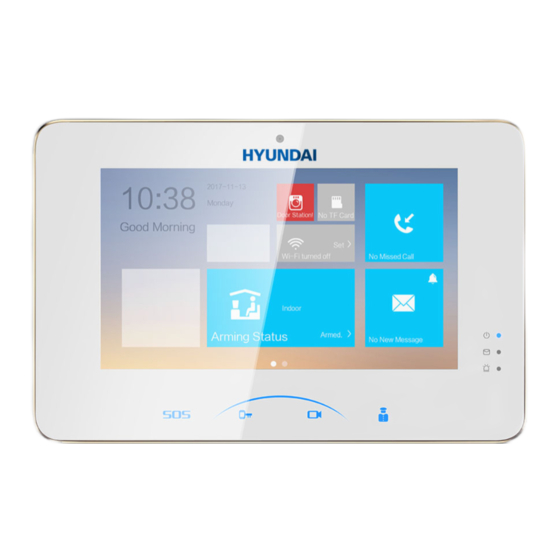
Video Intercom Indoor Station·User Manual You must create a password to activate the device for your first time usage and when it is not activated. Only when the device is activated, can you operate it locally and remotely. Here the activation interface of 8-series indoor station is taken as example. 6.2 User Interface Description 6.2.1 User Interface of Indoor Station Here the user interface of type III 6-series indoor station is taken as example. -
Page 24: User Interface Of Indoor Extension
Video Intercom Indoor Station·User Manual 6.2.2 User Interface of Indoor Extension Only 8-series indoor extensions support TF card. 6.2.3 Status of Indoor Station Table 6-1 Description of Status Icons Icon Definition Description The communication between indoor station, door station and master station is normal. Normal Status. -
Page 25: Status Of Indoor Extension
Video Intercom Indoor Station·User Manual Icon Definition Description station has not IP address. registered in the Network of SIP server is not available. Check SIP server. the SIP server network connection. SIP server communication is not available. Check if the SIP server IP address is correct. SIP server rejected to login the device. -
Page 26: Arming Status
Video Intercom Indoor Station·User Manual Icon Definition Description extension has station IP address. not connected Network of indoor station is not available. to the indoor Check the indoor station network connection. station. The indoor extension number conflicts with number of another indoor extension. TF card is inserted in the indoor station. - Page 27 Video Intercom Indoor Station·User Manual 2. Press Arm. 3. Enter the arm password to enable the arming status. 4. (Optional) Press a scene mode icon, and enter the arm password to change the scene mode of the indoor station. Example: After setting the arming status, press the Sleeping tab, and enter the arm password.
-
Page 28: Configuration Settings
Video Intercom Indoor Station·User Manual Only one arming mode can be set at one time. When you set another mode of arming status, the former one is disarmed automatically. If enabling the arming status successfully, you can hear a voice prompt “armed”, and the corresponding arming status will display on the main interface. -
Page 29: Set Sip Sever
Video Intercom Indoor Station·User Manual 2. Enable DHCP, then the indoor station can search and get an IP address automatically. Skip the following steps if you have set an IP address for the indoor station by DHCP function. 3. Set the IP address manually. 1) Tap to pop up the network parameters settings dialog box. - Page 30 Video Intercom Indoor Station·User Manual Rebooting the indoor station is required when you switch the SIP protocol between the private SIP protocol and the standard SIP protocol. All linked device IP should be configured again after you change the SIP protocol type. The indoor extension does not support SIP sever settings.
- Page 31 Video Intercom Indoor Station·User Manual 4. Tap SIP Sever, and enter the IP address of the SIP server. 5. Tap to save the SIP server added. Set Standard SIP With the standard SIP, your indoor station can connect to any intercom device, software client, and phones which also support the standard SIP.
- Page 32 Video Intercom Indoor Station·User Manual 3. Set VoIP account. The account you entered here must be the same with the account you added in the standard SIP server. The phone number should be a numeric, which is up to 16 digits. And the phone number will be the number you dial when you want to call the indoor station via standard SIP.
-
Page 33: Set Linked Device Ip
Video Intercom Indoor Station·User Manual 6.3.3 Set Linked Device IP Linked network parameters refers to the network parameters of devices (like door station, doorphone, master station, center, etc.), to which the indoor station is linked. Linked devices for the indoor station refers to door station, center, master station, and doorphone. -
Page 34: Set Indoor Station No
Video Intercom Indoor Station·User Manual Device Management (Standard SIP) 2. Tap Main Door Station to pop up the device information dialog box. 3. Select a door station type based on your actual door station type, and set the door station IP address. 6.3.4 Set Indoor Station No. -
Page 35: Add Camera
Video Intercom Indoor Station·User Manual 1. Tap Settings -> Configuration -> Local Info to go to the indoor station No. settings page. Default admin password is 888999. 2. Select Indoor Station to set the indoor station No. (Room No.) and the floor No. For Example: When set the Room No. -
Page 36: Synchronize Time
Video Intercom Indoor Station·User Manual Default admin password is 888999. 2. Tap Add device. 3. Tap Camera, and enter the corresponding information (device name, IP address, port No., password, etc.). 4. Tap to save the settings. 6.3.6 Synchronize Time Steps: 1. -
Page 37: Restore Indoor Station
Video Intercom Indoor Station·User Manual 3. Set the synchronizing interval, enter the IP address/domain of NTP server and port No., and select the time zone 6.3.7 Restore Indoor Station Steps: 1. Tap Settings -> Configuration -> Restore to enter the Restore Default Settings page. 2. - Page 38 Video Intercom Indoor Station·User Manual 2. Tap Admin Password, Duress Code, Unlock Password, or Arm/Disarm Password to enter corresponding pages. Admin Password: You cannot configure parameters for the indoor station without entering the admin password. Duress Code: When you are hijacked and forced to open the door, you can enter the duress code, and meanwhile an alarm is triggered to notify the management center secretly.
-
Page 39: Sound Settings
Video Intercom Indoor Station·User Manual 6. Tap to save the settings. The default admin password (configuration password) is 888999. The default arm/disarm password, and scene password are 123456. Indoor Extension only supports admin password and arm/disarm password. 6.5 Sound Settings Purpose: You can set the ringtone, ring duration, call forwarding time, volume of microphone and loudspeaker, enable/disable touch sound and auto-answer function on sound settings... -
Page 40: Do Not Disturb Settings
Video Intercom Indoor Station·User Manual Auto-answer function is only available to 8-series indoor stations with TF card function and 6-series indoor stations. Indoor Extension does not support the ring duration settings, call forwarding settings, or auto-answer function. 6.6 Do Not Disturb Settings Purpose: Two types of no disturbing mode can be configured: All day and Scheduled. -
Page 41: Zone Settings
Video Intercom Indoor Station·User Manual Indoor extension does not support Do Not Disturb Settings. 6.7 Zone Settings Purpose: You can set the zone type, alarm type and delay time and other parameters of 8 zones. Steps: 1. Get the zone settings interface: Settings -> Zone Settings. 2. -
Page 42: Arming Mode Settings
Video Intercom Indoor Station·User Manual 7 zone types are selectable: Panic Button, Door Magnetic, Smoke Detector, Active Infrared, Passive Infrared, Gas Detector, and Doorbell. 3 alarm types are selectable: 24h Alarm, Instant Alarm, and Delay Alarm. Set the alarm type as 24h alarm, and the zone will be armed for 24h. Set the alarm type as instant alarm, and the zone will alarm once it’s triggered. -
Page 43: System Maintenance
Video Intercom Indoor Station·User Manual For 24H alarm zone and smoke detector zone, even if it is disabled under current arming mode, the indoor station will still alarm when it is triggered. Arming mode settings should be configured with the settings of arming status on the user interface of the device. -
Page 44: Call Settings
Video Intercom Indoor Station·User Manual After enabling Clear Screen function, press and hold the Unlock key ( ) to exit the clear screen mode. 6.10 Call Settings 6.10.1 Add Contact Steps: 1. Press the tab on the user interface to enter the contact list interface. 2. -
Page 45: Call Resident
Video Intercom Indoor Station·User Manual Press the Call tab to start the video call with the contact. Press the Edit tab to modify the contact information. Press the Delete tab to delete the contact. Press the Clear tab to delete all contacts added in the indoor station. Indoor extension does not support this function. -
Page 46: Call Indoor Extension/Indoor Station
Video Intercom Indoor Station·User Manual 6.10.3 Call Indoor Extension/Indoor Station If you install indoor station and indoor extensions at home, you can call the indoor extension via your indoor station, and vice versa. Enter the indoor extension No. on the indoor station to start calling. Enter the numeric symbol 0 to call the indoor station from the indoor extension. - Page 47 Video Intercom Indoor Station·User Manual Call from Center (Master Station or Client Software) Call from Door Station On the call from door station interface, there are 2 unlock buttons: Unlock 1, and Unlock 2. When you press Unlock 1, the building gate will open by default, and when you press Unlock 2, the door connected to the door station with the secure control door unit will open.
-
Page 48: View Call Logs
Video Intercom Indoor Station·User Manual 6.10.6 View Call Logs Steps: 1. Press the tab on the touch screen to enter the call log interface. 2. Press tab Missed Call or All Calls to view missed call logs or all call logs. Indoor extension does not support this function. -
Page 49: Live View
Video Intercom Indoor Station·User Manual 6.11 Live View Make sure the IP camera or door station is well-connected. Make sure the indoor extension and the indoor station are well-connected. The type III 6-series indoor station only supports getting the live view of IP camera. Purpose: On the live view interface, you can monitor the live view of added door station and IP camera. -
Page 50: Information Management
Video Intercom Indoor Station·User Manual On the call from door station interface, there are 2 unlock buttons: Unlock 1, and Unlock 2. When you press Unlock 1, the building gate will open by default, and when you press Unlock 2, the door connected to the door station with the secure control door unit will open. - Page 51 Video Intercom Indoor Station·User Manual Indoor extension only supports alarm log and capture log. For 8-series indoor stations, it requires TF card for saving the notice, visitor messages and capture logs of the indoor stations, and requires the internal memory of the indoor station to save the alarm log.
-
Page 52: Remote Operation Via Batch Configuration Tool
Video Intercom Indoor Station·User Manual 7 Remote Operation via Batch Configuration Tool You can configure and operate the video intercom devices via Batch Configuration Tool. Default parameters of indoor station are as follows: Default IP Address: 192.0.0.64. Default Port No.: 8000. Default User Name: admin. -
Page 53: Edit Network Parameters
Video Intercom Indoor Station·User Manual STRONG PASSWORD RECOMMENDED– We highly recommend you create a strong password of your own choosing (Using a minimum of 8 characters, including at least three of the following categories: upper case letters, lower case letters, numbers, and special characters.) in order to increase the security of your product. -
Page 54: Add Device
Video Intercom Indoor Station·User Manual The default port No. is 8000. The default IP address of the indoor station is 192.0.0.64. After editing the network parameters of device, you should add the devices to the device list again. Enable DHCP, and the software can obtain network parameters for the device automatically. -
Page 55: Add By Ip Address
Video Intercom Indoor Station·User Manual 2. Click the button to pop up the login dialog box. 3. Enter the user name and password. 4. Click the OK button to save the settings. Only devices successfully logged in will be added to the device list for configuration. If you add devices in batch, please make sure selected devices have the same user name and password. -
Page 56: Add By Ip Segment
Video Intercom Indoor Station·User Manual 4. Click OK to add the device to the device list. You cannot add the device(s) to the device list if the user name and password are not identical. When you add devices by IP Address, IP Segment or Port No., the devices should be online devices. -
Page 57: Configure Devices Remotely
Video Intercom Indoor Station·User Manual 5. Click the OK button to search and add the devices whose IP addresses are within the range of the defined IP segment to the device list. 7.4 Configure Devices Remotely In the device list area, select a device and click to enter the remote configuration interface. - Page 58 Video Intercom Indoor Station·User Manual Time Steps: 1. Click Time to enter the device time settings interface. 2. Select Time Zone or Enable NTP. Time Zone Select a time zone from the drop-down list menu. Click the Synchronization button. Check the checkbox of Enable NTP to enable NTP. Enter the server address, NTP port, and synchronization interval.
- Page 59 Video Intercom Indoor Station·User Manual System Maintenance Purpose: You can reboot, restore the device, upgrade the device, and change the device system language on the system maintenance interface. Steps: 1. Click System Maintenance to enter the system maintenance interface. 2. Click Reboot and the system reboot dialog box pops up. Click Yes to reboot the system.
- Page 60 Video Intercom Indoor Station·User Manual 6. Click Export Configuration File and the export file window pops up. Select the saving path of remote configuration files and click Save to export the configuration file. to select the upgrade file and click Upgrade to remote upgrade the device. 7.
- Page 61 Video Intercom Indoor Station·User Manual 8. Select a language, and click Save to change the device system language. The device supports 5 languages: English, Russian, French, Portuguese, and Spanish. Rebooting the device is required after you change the system language. User Purpose: You can edit the password for logging in the device.
-
Page 62: Video Intercom
Video Intercom Indoor Station·User Manual 3. Enter the new password, and confirm it. 4. Click Save to realize the editing of password. The new password and confirm password should be identical. After editing the password of device, click button from the device list, the added device will not be there. - Page 63 Video Intercom Indoor Station·User Manual 2. Select the device type from the drop-down list, and set the corresponding information. 3. Click Save to enable the device number configuration. Time Parameters 1. Click Time Parameters to enter time parameters settings interface. 2.
- Page 64 Video Intercom Indoor Station·User Manual Zone 1. Click the Zone Alarm button to enter zone settings interface. 2. Select a zone type from the drop-down list menu. 3. Select an alarm mode from the drop-down list menu. 4. Set the zone status: NO or NC. 5.
- Page 65 Video Intercom Indoor Station·User Manual When the zone type is set to be Delay Alarm, only under arming mode, the indoor station will receive alarm message when the detector is triggered. Under disarming mode, it will not receive alarm message when the detector is triggered. After setting enter delay time, if OK is pressed within the enter delay time after the alarm, the alarm event will not be uploaded to the management center;...
- Page 66 Video Intercom Indoor Station·User Manual Indoor extension does not support this function. Export and Import Added Device Information Steps: 1. Click Export to export the added device information file. 2. Edit parameters of added devices in batch in the exported file. 3.
- Page 67 Video Intercom Indoor Station·User Manual Volume Input and Output Step: 1. Click Volume Input/Output to enter the volume input and output interface. 2. Slide the slider to adjust the volume input and volume output. 3. Click Save to enable the settings. Ring Import Click Ring Import to enter the ring configuration interface.
-
Page 68: Network
Video Intercom Indoor Station·User Manual Network 7.4.3 Local Network Configuration Steps: 1. Click Local Network Configuration to enter local network configuration interface. 2. Enter the local IP address, subnet mask, gateway address, and port No. 3. Click Save to enable the settings. The default port No. - Page 69 Video Intercom Indoor Station·User Manual 2. Enter the master station IP address, (main) door station IP address, SIP server IP address, management center IP address, and doorphone IP address. 3. Select the main door station type from the drop-down list. 4.
-
Page 70: Video Display
Video Intercom Indoor Station·User Manual Video Display 7.4.4 Click Video Display -> Video Parameters to adjust the relevant parameters for the video. Only indoor station equipped with a physical camera has the video parameters settings. 7.5 Video Intercom Device Set-up Tool Purpose: You can assign the device to the community, activate and set the device, and configure the network parameters and linked network parameters for the device by using the... -
Page 71: Set Indoor Station
Video Intercom Indoor Station·User Manual Set Indoor Station 7.5.2 Purpose: You can activate the online indoor station, and configure the room No. for the online indoor station. Steps: 1. Press the Indoor Station tab to switch to the indoor station configuration interface. - Page 72 Video Intercom Indoor Station·User Manual 2. Select a community, and enter the indoor station start IP address, and then click the Calculate button to generate the indoor station end IP address and indoor station room No. (like 1-1-1-1-2) automatically. 3. Set the main door station parameters: door station type (door station for unit, or door station for villa), main door station IP address.
-
Page 73: Batch Upgrading
Video Intercom Indoor Station·User Manual When the device is successfully configured, it prompts the note: Configuring main door station parameters succeeded. 7.6 Batch Upgrading In the device list area, click to enter the batch upgrading interface. Add Devices for Upgrading 7.6.1 You should add the device to the batch upgrading tool first before upgrading the device. - Page 74 Video Intercom Indoor Station·User Manual 2. Select a device, enter the user name and password, and click the Login Device button. 3. Click the Add Device button, and the device is added to the batch upgrading tool. Adding by IP Address/IP Segment Steps: 1.
-
Page 75: Upgrade By File
Video Intercom Indoor Station·User Manual 2. Enter the corresponding information (IP address, user name, password, start IP address, end IP address). 3. Click the Add button. Upgrade by File 7.6.2 You can upgrade indoor stations in batch via the Batch Upgrading tool. The indoor station support Upgrading by File, that is, you can upgrade indoor stations in batch via the local upgrade files. - Page 76 Video Intercom Indoor Station·User Manual 3. Open the upgrading file, and click the Upgrade button.
-
Page 77: Remote Operation Via Hyu-Connect App
Video Intercom Indoor Station·User Manual 8 Remote Operation via Hyu-Connect app The Video Intercom module provides remote control and configuration on video intercom products via the Hyu-Connect app software. 8.1 System Configuration Purpose: You can configure the video intercom parameters accordingly. Steps: 1. -
Page 78: Device Management
Video Intercom Indoor Station·User Manual 8.2 Device Management Purpose: Device management includes device activation, adding device, editing device, and deleting device, and so on. After running the Hyu-Connect app, video intercom devices should be added to the client software for remote configuration and management. 8.2.1 Add Video Intercom Devices You can add at most 512 indoor stations and master stations in total to the Hyu-Connect app, and add at most 16 door stations to the Hyu-Connect app. - Page 79 Video Intercom Indoor Station·User Manual manually, please refer User Manual of Hyu-Connect app (Video Intercom) V2.4.2 in the disk for detail steps. Steps: 1. Click the icon on the control panel, or click Tools->Device Management to open the Device Management page. 2.
-
Page 80: Modify Network Information
Video Intercom Indoor Station·User Manual Add Multiple Online Devices If you want to add multiple online devices to the client software, click and hold Ctrl key to select multiple devices, and click Add to Client to open the device adding dialog box. In the pop-up message box, enter the user name and password for the devices to be added. -
Page 81: Reset Password
Video Intercom Indoor Station·User Manual You should enter the admin password of the device in the Password field of the pop-up window to modify the parameters. 8.2.3 Reset Password According to the different video intercom devices, the software provides two different methods for restoring the default password or resetting the password. - Page 82 Video Intercom Indoor Station·User Manual 1. Click Export to save the device file on your computer. 2. Send the file to our technical engineers. 3. Our technical engineer will send you a file to you. After receiving a file from the technical engineer, select Import File from Key Importing Mode drop-down list and click to import the file.
-
Page 83: Remote Configuration
Video Intercom Indoor Station·User Manual 1. Click Export to save the device file on your computer. 2. Send the file to our technical engineers. 3. Click Import and select the file received from the technical engineer. 4. Input new password in text fields of Password and Confirm Password. 5. - Page 84 Video Intercom Indoor Station·User Manual Once the scene is configured, you cannot change it later. Click - > to enter the Person and Card Management interface. The interface is divided into two parts: Organization Management and Person Management. Organization You can add, edit, or delete the organization as Management desired.
-
Page 85: Organization Management
Video Intercom Indoor Station·User Manual 8.4.1 Organization Management Add Organization Steps: In the organization list on the left, you should add a top organization as the parent organization of all organizations. Click Add to pop up the adding organization interface. Enter the Organization Name as desired. - Page 86 Video Intercom Indoor Station·User Manual Up to 10,000 persons or cards can be added. Add Person Person information is necessary for the video intercom system. And when you set linked device for the person, the intercom between intercom devices can be realized. Steps: Select an organization in the organization list and click Add on the Person panel to pop up the adding person dialog.
- Page 87 Video Intercom Indoor Station·User Manual The picture should be in *.jpg format. (Optional) You can also click Take Phone to take the person’s photo with the PC camera. Set linked device for the person. Click Details. Set the linked devices Linked Device: You can bind the indoor station to the person.
- Page 88 Video Intercom Indoor Station·User Manual Select Normal Card. Enter the password of the card itself in the Card Password field. The card password should contain 4 to 8 digits. Enter Card Number manually. Click OK and the card(s) will be issued to the person. Import and Export Person Information The person information can be imported and exported in batch.
- Page 89 Video Intercom Indoor Station·User Manual Click OK to start exporting. Importing Person: You can import the Excel file with persons information in batch from the local PC click Import Person button. You can click Download Template for Importing Person to download the template first.
- Page 90 Video Intercom Indoor Station·User Manual This function is only supported by the device the connection mothod of which is TCP/IP when adding the device. Steps: In the organization list on the left, click to select an organization to import the persons.
- Page 91 Video Intercom Indoor Station·User Manual To delete the person, select a person and click Delete to delete it. If a card is issued to the current person, the linkage will be invalid after the person is deleted. Change Person to Other Organization You can move the person to another organization if needed.
-
Page 92: Video Intercom
Video Intercom Indoor Station·User Manual Select Normal Card. Enter the password of the card itself in the Card Password field. The card password should contain 4 to 8 digits. Enter the card quantity issued for each person. For example, if the Card Quantity is 3, you can read or enter three card No. for each person. -
Page 93: Call Indoor Station Via Hyu-Connect App
Video Intercom Indoor Station·User Manual Click -> on the left icon bar to enter the Video Intercom interface. 8.5.1 Call Indoor Station via Hyu-Connect app Steps: Click on the left icon bar to enter the Video Intercom interface. Select a resident and click the icon in the Call Household column to start calling the selected resident. -
Page 94: Receive Call From Indoor Station/Door Station
Video Intercom Indoor Station·User Manual Click to adjust the volume of the loudspeaker. Click to hang up. Click to adjust the volume of the microphone. One indoor station can only connect with one client software. You can set the maximum ring duration ranging from 15s to 60s, and the maximum speaking duration ranging from 120s to 600s via the Remote Configuration of indoor station. - Page 95 Video Intercom Indoor Station·User Manual Click Answer to answer the call. Or click Hang Up to decline the call. After you answer the call, you will enter the In Call window. Click to adjust the volume of the loudspeaker.
-
Page 96: View Live Video Of Door Station And Outer Door Station
Video Intercom Indoor Station·User Manual Click to hang up. Click to adjust the volume of the microphone. For door station, you can click to open the door remotely. One video intercom device can only connect with one client software. The maximum ring duration can be set from 15s to 60s via the Remote Configuration of the video intercom device. -
Page 97: View Call Logs
Video Intercom Indoor Station·User Manual You can click Unlock on the menu to open the door remotely. 8.5.4 View Call Logs Purpose: You can check all the call logs, including dialed call logs, received call logs and missed call logs. You can also directly dial via the log list and clear the logs. Steps: In the Video Intercom page, click the Call Log tab to enter the Call Log page. - Page 98 Video Intercom Indoor Station·User Manual Click New Notice on the left panel to create a new notice. Edit the notice on the right panel. Click icon on the Send To field to pop up the Select Resident dialog. Check the checkbox(es) to select the resident(s).
-
Page 99: Search Video Intercom Information
Video Intercom Indoor Station·User Manual Or you can check the All checkbox to select all the added residents. Click OK to save the selection. Enter the subject on the Subject field. Up to 63 characters are allowed in the Subject field. Click in the Type field to unfold the drop-down list and select the notice type. - Page 100 Video Intercom Indoor Station·User Manual Set the search conditions, including call status, device type, start time and end time. Call Status: Click to unfold the drop-down list and select the call status as Dialed, Received or Missed. Or select All to search logs with all statuses. Device Type: Click to unfold the drop-down list and select the device type as Indoor Station, Door Station, Outer Door Station or Analog Indoor...
- Page 101 Video Intercom Indoor Station·User Manual In the Information Search page, click Unlocking Log tab to enter the Unlocking Log interface. Set the search conditions, including unlocking type, device type, start time and end time. Unlocking Type: Click to unfold the drop-down list and select the unlocking type as Unlock by Password, Unlock by Duress, Unlock by Card, Unlock by Resident or Unlock by Center.
- Page 102 Video Intercom Indoor Station·User Manual (Optional) Click Export to export the unlocking logs to your PC. Search Notice Steps: In the Information Search page, click the Notice tab to enter the Notice interface. Set the search conditions, including notice type, subject, recipient, start time and end time.
- Page 103 Video Intercom Indoor Station·User Manual You can view and edit the notice details, check the sending failed/sent succeeded/unread users, and resend the notice to sending failed/unread users. (Optional) Click Export to export the notices to your PC.
-
Page 104: Accessing Via Hyu-Connect App Client Software
Video Intercom Indoor Station·User Manual 9 Accessing via Guarding Vision Mobile Client Software The Guarding Vision mobile client software supports the iOS system and Android system both. The basic operations of the client software are similar on the iOS system and on the Android system. - Page 105 Video Intercom Indoor Station·User Manual You should register the software first before logging in the software. Two ways of registration are available: Registration via Telephone No., and Registration via E-Mail Address. Here we take Registration via Telephone No. as example to introduce registering an account in the software.
- Page 106 Video Intercom Indoor Station·User Manual 4. Select a target region, enter a valid mobile phone No., and tap the Get Verification Code button. The verification code will be sent to your phone. 5. Enter the received verification code, and tap the Next button to enter the account creating interface.
-
Page 107: Log In Software
Video Intercom Indoor Station·User Manual 9.3 Log in Software Steps: 1. Tap the icon to run the software. 2. Enter the user name/e-mail address, and enter the password. 3. Tap the Login button to log in the software. If you want to login via mobile phone No., please tap Login with mobile phone number. -
Page 108: Add Device Via Serial No
Video Intercom Indoor Station·User Manual 9.4.2 Add Device via Serial No. Steps: 1. On the Home screen, tap the icon , and tap the icon 2. Enter the serial No. of the device to pop up the device information page, and tap the Add button. -
Page 109: Live View And Remote Unlocking
Video Intercom Indoor Station·User Manual The serial No. of the device is on the label stuck on the rear panel of the device. The default device verification code is ABCDEF. 9.5 Live View and Remote Unlocking After adding the device, go the Home page, and tap a camera to enter the live view interface. - Page 110 Video Intercom Indoor Station·User Manual Table 9-1 Icon Description Keys Description Enable the live view. Disable the live view. Enable/disable the audio. Switch to the full-screen mode. Switch to the 4-screen mode. Zoom in. Remote unlock. Capture the live view image. Enable/disable recording.
-
Page 111: Appendix
Video Intercom Indoor Station·User Manual Appendix Installation Notice While installing the indoor station, please make sure that the distance between any two devices is far as possible to avoid the howling and echo. The distance between two devices is recommended to be more than 10 meters. Here the devices refer to indoor station, outdoor station and master station. - Page 112 www.hyundai-security.tech Licensed by HYUNDAI Corporation, Korea...
Need help?
Do you have a question about the HYU-559 and is the answer not in the manual?
Questions and answers