Table of Contents
Advertisement
Quick Links
Advertisement
Table of Contents

Related Manuals for HIKVISION DS-KB2421-IM


Summary of Contents for HIKVISION DS-KB2421-IM
- Page 1 Video Door Phone Door Station and Indoor Station User Manual UD05714B...
- Page 2 Trademarks and other Hikvision marks are the property of Hikvision and are registered trademarks or the subject of applications for the same by Hikvision and/or its affiliates. Other trademarks mentioned in this manual are the properties of their respective owners. No right of license is given to use such trademarks without express permission.
- Page 3 Video Door Phone·User Manual Regulatory Information FCC Information Please take attention that changes or modification not expressly approved by the party responsible for compliance could void the user’s authority to operate the equipment. FCC compliance: This equipment has been tested and found to comply with the limits for a Class A digital device, pursuant to part 15 of the FCC Rules.
- Page 4 Video Door Phone·User Manual Symbol Conventions The symbols that may be found in this document are defined as follows. Symbol Description Provides additional information to emphasize or supplement important points of the main text. Indicates a potentially hazardous situation, which if not avoided, could result in equipment damage, CAUTION data...
- Page 5 Video Door Phone·User Manual Preventive and Cautionary Tips Please use the provided glove when open up the device cover, avoid direct contact with the device cover, because the acidic sweat of the fingers may erode the surface coating of the device cover. ...
-
Page 6: Table Of Contents
Video Door Phone·User Manual Table of Contents 1 Introduction ....................1 1.1 Overview ......................1 1.2 Features ......................1 2 Appearance Description ................2 2.1 Indoor Station ..................... 2 2.2 Door Station ......................2 3 Terminals and Wirings .................. 3 3.1 Terminals and Interfaces .................. -
Page 7: Introduction
Video Door Phone·User Manual 1 Introduction 1.1 Overview The video door phone is composed of a four-wire indoor station and a four-wire door station. Featuring in the convenient installation and easy operation, it is mainly applied in the buildings for improving the living security. -
Page 8: Appearance Description
Video Door Phone·User Manual 2 Appearance Description 2.1 Indoor Station Table 2-1 Components Description Description Power Supply Indicator Call Accept/Decline Key Unlock Key Live View Key Switch Key LCD Screen Microphone Terminals and Interfaces Loudspeaker Volume Control Knob Figure 2-1 Indoor Station Appearance 2.2 Door Station Table 2-2 Components Description Description... -
Page 9: Terminals And Wirings
Video Door Phone·User Manual 3 Terminals and Wirings 3.1 Terminals and Interfaces 3.1.1 Terminals of Indoor Station On the rear panel of the indoor station, there are 4 groups of four-wire terminals for connecting indoor station or door station, 1 terminal for accessing the camera, and 1 terminal for power supply. -
Page 10: Wiring Description
Video Door Phone·User Manual Figure 3-2 Wire of Door Station Table 3-2 Descriptions of Terminals and Interfaces (Door Station) Color Name Interface Description Power Supply (from Indoor Station) Wire Blue CVBS Video Output Group (Four-Wir Yellow AUIDO Audio Input/Output Black Grounding Signal Door Lock Relay Output/Normally Open Wire... - Page 11 Video Door Phone·User Manual NOTE According to different transmission distances among door stations and indoor stations, different RVV4 cable specifications are demanded. Transmission Distance (TD) RVV4 Cable Specification TD ≤ 10 m RVV4 * 0.2 mm ^2 10 m < TD ≤ 30 m RVV4 * 0.5 mm ^2 30 m <...
-
Page 12: Wiring 1 (1 Door Station And 1 Indoor Station)
Video Door Phone·User Manual 3.2.1 Wiring 1 (1 Door Station and 1 Indoor Station) CAUTION Do not pull power cables on the rear panel of the door station hard to avoid the disconnection of power cables. Use the insulated tape to tape the bare wires, so as to avoid the short circuit. Analog Camera Electric Bolt Red ——... -
Page 13: Wiring 2 (1 Door Station And 3 Indoor Stations)
Video Door Phone·User Manual 3.2.2 Wiring 2 (1 Door Station and 3 Indoor Stations) CAUTION Do not pull power cables on the rear panel of the door station hard to avoid the disconnection of power cables. Use the insulated tape to tape the bare wires, so as to avoid the short circuit. Electric Bolt Red ——... -
Page 14: Wiring 3 (2 Door Stations And 3 Indoor Stations)
Video Door Phone·User Manual 3.2.3 Wiring 3 (2 Door Stations and 3 Indoor Stations) CAUTION Do not pull power cables on the rear panel of the door station hard to avoid the disconnection of power cables. Use the insulated tape to tape the bare wires, so as to avoid the short circuit. Electric Bolt Electric Bolt Red ——... -
Page 15: Installation
Video Door Phone·User Manual 4 Installation Before you start: Make sure the device in the package is in good condition and all the assembly parts are included. The power supply the indoor station supports is 12 VDC. Please make sure your power supply matches your indoor station. -
Page 16: Door Station Installation
Video Door Phone·User Manual Wall Mounting Plate Screws Junction Figure 4-2 Installing the Plate 3. Hook the indoor station to the wall mounting plate tightly by inserting the plate hooks into the slots on the rear panel of the indoor station, during which the lock catch will be locked automatically. - Page 17 Video Door Phone·User Manual Wall Mounting (Door Station) You can follow the following steps to install the door station. Steps: Figure 4-4 Install the Door Station 1. Fix the wall mounting plate to the wall with 2 screws. 2. Hook the door station to the shield tightly by inserting the hooks of shield panel into the slots on the rear panel of the door station.
-
Page 18: Local Operation
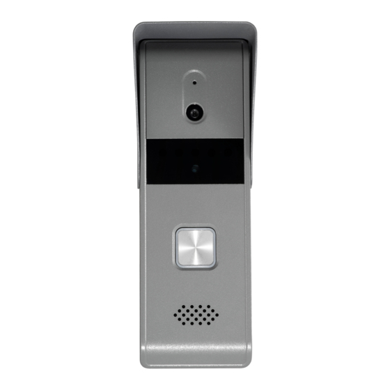
Video Door Phone·User Manual 5 Local Operation 5.1 Door Station Local Operation Steps: Press the call button to call the resident. When press the call button to call the resident, the maximum ring duration of the indoor station is 30s. Figure 5-1 Call Button of Door Station 5.2 Indoor Station Local Operation Table 5-1 Indoor Station Local Operation Description... -
Page 19: Appendix
Video Door Phone·User Manual Appendix Installation Notice While installing the indoor station, make sure that the distance between any two devices is far enough to avoid the howling and echo. The distance between two devices is recommended to be longer than 10 meters. NOTE Here devices refer to indoor stations, and door stations. - Page 20 Video Door Phone·User Manual...
Need help?
Do you have a question about the DS-KB2421-IM and is the answer not in the manual?
Questions and answers