CAME GARD Series Manual
Hide thumbs
Also See for GARD Series:
- Installation manual (97 pages) ,
- Manual (24 pages) ,
- Standard installation (12 pages)

Related Manuals for CAME GARD Series


Summary of Contents for CAME GARD Series
- Page 1 GARD SERIE Documentazione Tecnica ARRIER rev. 03/2001 G12000 © CAME CANCELLI AUTOMATICI 119G56-GB CANCELLI AUTOMATICI...
-
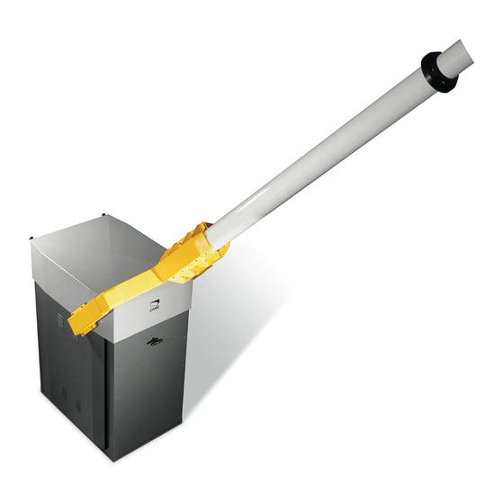
Page 2: General Characteristics
- Hardware and accessories for mounting the barrier bar. - Fixed support for the barrier. I I I I I mportant: For easy installation and maintenance, be sure to use CAME original control equipment, safety systems and accessories. TECHNICAL CHARACTERISTIC... - Page 3 DESCRIPTION OF MAIN COMPONENTES 24 VDC motors; non-reversible reduction gear with die-cast aluminium REDUCTION GEAR UNIT housing; uses worm gear reduction system which is permanently lubricated with liquid grease. In forged, galvanised steel; adjustment rods in drawn TRANSMISSION LEVERS hexagonal metal; self-lubricating joints. In C40 recycled steel, mounted on single-unit ROTATION SHAFT supports with terminal flanges for installation of...
- Page 4 DESCRIPTION OF ASSEMBLY PROCEDURE 1 - ASSEMBLY OF FIXED STRUCTURES, MARKING a) determine the desired positions for the housing as well as for the fixed support for the barrier bar; mark the longitudinal and transverse axes of the barrier. axis of support axis of for barrier bar barrier bar rotation...
- Page 5 DESCRIPTION OF ASSEMBLY PROCEDURE DESCRIPTION OF ASSEMBLY PROCEDURE DESCRIPTION OF ASSEMBLY PROCEDURE DESCRIPTION OF ASSEMBLY PROCEDURE DESCRIPTION OF ASSEMBLY PROCEDURE 2 - PRELIMINARY ASSEMBLY OF THE BARRIER BAR FRONT TUBE depth of insertion END CAP fixed length 6200 mm REAR TUBE a) use the indicated formula to determine length LTP of the rear tube (Ø100 mm), cut the tube to the correct length and install the end cap.
- Page 6 DESCRIPTION OF ASSEMBLY PROCEDURE 3 - INSTALLING THE BARRIER a) remove the cover of the housing (by lifting) and remove the sides of the housing (by raising and withdrawing them from below); clean the cement bases and free the bolts on the anchor stays by removing the protection tape and nuts;...
- Page 7 DESCRIPTION OF ASSEMBLY PROCEDURE 4- ASSEMBLING THE COUNTERWEIGHTS; ADJUSTING AND BALANCING THE BARRIER BAR a) install the release handle, b) insert the counterweight turn the safety key and rotate plates on the support, the handle to alternatively on the release the left and right, until gear the bar shows...
-
Page 8: Main Components
ZL37B CONTROL PANEL DESCRIPTION & CONTROL LOGIC MAIN COMPONENTS 1) Transformer 2) Connectors for power Rallentamento Velocità supply motor Deceleration Speed Ralentissement Vitesse 3) Terminal block for motor Geschw. Geschw. Abnahme Velocidad Deceleración connections 4) 2A accessories fuse 5) Amperometric sensitivity adjustment (trimmer SENS) "B"... - Page 9 QUADRO ELETTRICO ZL37B ALLACCIAMENTI & REGOLAZIONI ELETTRONICHE E + 10-11 1 2 C1C5 FA FC F PT L1 L2 24V A.C. motor Connection limit switch deceleration opens Connection limit switch deceleration closes 230V A.C. power Accessory power: 24V A.C. max. 40W during movement (e.g.
- Page 10 ZL37B CONTROL PANEL SELECTION .UNCTION Vel. Rall. 9 10 9 10 activated deactivated activated deactivated 1 = function 5 = funcion automatic closure flashing light en opening and closing - deactivated immedia- te closure (8 ON) activated deactivated activated deactivated 6 = function 2 = function obstacle detection...
-
Page 11: Programming The Remote Control
ZL37B CONTROL PANEL ADJUSTMENTS Vel. Rall. T.C.A. SENS. REGOLAZIONE TRIMMERS TRIMMERS ADJUSTMENT RÉGLAGE TRIMMERS EINTELLUNG TRIMMERS REGULACIÓN TRIMMERS 9 10 Trimmer SENS. = Adjustment of amperometric sensitivity min./max. Trimmer T.C.A. = Adjustment automatic closing time from a minimun of 0 seconds to a maximum of 120 seconds. - Page 12 TRANSMITTER ENCODING QUARTZ STANDARD ENCODING PROCEDURE code T262L/M-T264L/M-T2622M T302L/M-T304L/M-T3022M 1.assign a code (also on file) 2.connect encoding jumper J 3.register code 4.disconnect jumper J Press P1 or P2 in sequence in order to register the code; at the tenth pulse, a double beep will confirm that registration has occurred T2622M - T3022M P1=OFF...
- Page 13 ATOMO AT01 - AT02 see instruction sheet inside the pack of AF43SR circuit card T432M - T312M set the code to dip-switch C and channel to D (P1=CH1 and P2=CH2, default setting) T434M - T314M T432S P1=CH1 P2=CH2 P3=CH3 see instructions on pack set code only P4=CH4 T132...
- Page 14 CODE STORAGE - While holding down key "CH" signal LED flashing (Fig.1), press the control key on the transmitter: the lights up of LED sign the code stored (Fig.2). IMPORTANT: Do not store the code on the circuit card unless the barrier is closed. N.B.: If you wish to change the code on your transmitters in the future, simply repeat the procedure described above.
- Page 15 ZL37B CONTROL PANEL CONNECTIONS .OR 2 COMBINED MOTORS CONTROLLED TOGETHER 1) On one of the two control panels, set Dip 7 to ON in order to select the motor Rallentamento Velocità Deceleration Speed Ralentissement Vitesse Geschw. Geschw. Abnahme controlled externally (slave). Velocidad Deceleración "B"...
- Page 16 ANTERRE CEDEX CERTIFICATO (+39) 02 26708293 (+39) 02 25490288 (+33) 01 46130505 (+33) 01 46130500 UMERO ERDE 800 295830 CAME SUD S.R.L. ___________________NAPOLI CAME GMBH________K (STUTTGART) ORNTAL BEI (+39) 081 7524455 (+39) 081 7529109 (+49) 07 11839590 (+49) 07 118395925 www.came.it CAME (AMERICA) L.L.C.____________MIAMI (FL)
- Page 17 Important Information Gate automation equipment must be installed in accordance with all current legislation; namely Machinery Directive 98/37/EC and BS EN12453. BRUNDLE...
Need help?
Do you have a question about the GARD Series and is the answer not in the manual?
Questions and answers