CAME GARD Series Installation Manual
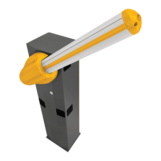
Street barriers
Hide thumbs
Also See for GARD Series:
- Installation manual (97 pages) ,
- Manual (24 pages) ,
- Standard installation (12 pages)
Table of Contents
Advertisement
Quick Links
Advertisement
Table of Contents

Related Manuals for CAME GARD Series


Summary of Contents for CAME GARD Series
- Page 1 STREET BARRIERS 1 19 GV18 EN INSTALLATION MANUAL G3250 English...
-
Page 2: Table Of Contents
Index Legend of symbols p. 4 Intended use and limitis to use p. 4 Intended use p. 4 Limits to use p. 4 Description p. 4 Technical data p. 4 Description of parts p. 5 Dimensions p. 6 Installation p. 6 Preliminary checks p. - Page 3 • Use this product only for the specifi c purpose for which it is designed. Any ponents, all fastening points and devices, the cables and accessible connec- other use is, therefore, dangerous. CAME Cancelli Automatici S.p.A. is not lia- tions. Maintain all hinges and joints well-greased and the boom-attachment ble for any damage resulting from improper, wrongful or unreasonable use.
-
Page 4: Legend Of Symbols
Intended use The 001G3250 barrier is designed and built by © CAME Cancelli Automatici S.p.A. in compliance with current regulations on safety con- cerning the use of parking facilities in private, public, residential and areas with high fl ow densities. -
Page 5: Description Of Parts
Description of parts BARRIER Cabinet Hatch lock with customised key Transmission shaft Gearmotor Arm-attachment cover Quadro comando Anti-shearing protective cover Balancing spring Gearmotor release with customised key 10. Inspection hatch ACCESSORIES 11. Cable cover profile 12. Semi-elliptical tube arm 13. Anti-impact profile 14. -
Page 6: Dimensions
Dimensions max. 3250 Installation Installation must be carried by skilled, qualified technicians in accordance with current regualtions. Preliminary checks Before beginning to install, the following is necessary: Set up proper omnipolar cut-off device, with more than 3mm of distance between contacts, with sectioned power source; •... -
Page 7: Types Of Cables And Thicknesses
Types of cables and thicknesses Cable length Cable length Cable length Connection Cable type 1 < 10 m 10 < 20 10 ÷ 20 m 20 < 30 20 ÷ 30 m 230 V power source to control panel 3G x 1.5 mm 3G x 1.5 mm 3G x 2.5 mm Motor power supply (V) 24 V... -
Page 8: Preparing The Anchoring Base
Preparing the anchoring base The following illustrations are just examples, in that the space for securing the operator and accessories depends on the overall measurements.It is up to the installer to choose the most suited solution. Dig a hole for the anchoring base, set the any corrugated tubes for connections coming from the juction pit. -
Page 9: Installing The Operator
N.B.: install the cabinet with the inspection door facing an easily accessible direction. Washer To change rotation at a later date, request documentation from authorised dealer or directly contact the Came office near you (see last page or www.came.com) Entrace Entrance... - Page 10 Length of arm 230 mm Calculate the am length and that of the anti-impact profi le by using as reference the passage width room.If necessary, cut any extra parts. passage width room (3250 mm max.) 30 mm Length of anti-impact profile Insert the anti-impact profi...
- Page 11 Insert the insulation cap into one of the two ends of the luminous cord.Insert by pressure the luminous cord into the arm raceway, as shown in the fi gure. Insert the power cable through the central hole in the transmission arm plate.Perforate the control panel at one of the pre-perforated points and fi...
- Page 12 Insert the arm into the arm-attachment cap making sure that the power cable is inside the arm raceway. Connect the power cable jack to the luminous cord.If the luminous cord does not work invert/turn the jack, then isolate the junction point with a thermo shrinking sheath.
- Page 13 Position the arm vertically to secure between the arm-attachment cap and the transmission shaft plate. UNI 5931 M8x12 Secure the rod with Insert and secure the anti-shearing protective cover onto the arm- attachment cap.
-
Page 14: Arm Balancing
Arm balancing Release the gearmotor and loosen nut on the rod. Securing nut RELEASE Manually turn the balancing spring to increase or reduce the traction force so that the arm balances at 45°. Secure the nut of the bar and lock the gearmotor. -
Page 15: Adjusting Endpoints
Adjusting endpoints N.B.: to do after electrical connections are made to the control panel. Close the inspection door and power up the system.Activate the arm to check whether it is parallel to the road surface when close and at about 89° when open. To correct the vertical position (=opening), lower the barrier arm, open the inspection door and rutn the opening mechanical stop either clockwise or counterclockwise, then secure the stop with the counter nut. -
Page 16: Manual Release Of The Barrier Arm
Description of the control panel Designed and made by CAME Cancelli Automatici S.p.A.The control Types of command: panel is powered by 230 V AC, at 50 / 60 Hz frequency. - opening/closing;... -
Page 17: Main Component Parts
Main component parts 1 - Accessories fuse 11 - Warning LED for radio code/automatic closing 2 - Line fuse 12 - Adjustment connectors for speed and deceleration 3 - control panel fuse 13 - Connection connectors for 002LB38 card (battery charger) 4 - motor fuse 14 - Selection jumper for command type for button on 2-7 5 - Accessories terminals... -
Page 18: Power Source And Accessories
Power source and accessories Terminals for powering accessories: - for 24 V AC at normal operation; - for 24 V DC with battery operation; Overall allowed power:40 W 230 V AC power source, 50/60 MHz frequency Eyelet with screw and washer for ground connection of Command devices Stop button (N.C. -
Page 19: Warning Devices
Warning devices Flashing light and luminous cord (contact voltage rating: 24V -23 W max. - Both fl ash on and off during barrier opening and closing. Warning light when barrier arm is open(contact voltage rating: 24V -3W max.)) Warns that the barrier arm is open. Safety devices DELTA S photocells Reopening when closing (N.C.) Contact... -
Page 20: Selecting Functions
Selecting functions Default setting 1 ON - Automatic closing- The automatic closing timer activates upon upon full opening.The preset time is adjustabel, but it's in any case subject to any safety device intervention and does not activated after a Total Stop or in case of power failure (1 OFF - deactivated); 2 OFF - Open-Close with button (2-7) and/or transmitter (requires radiofrequency card). -
Page 21: Activating The Radio Command
Activating the radio command Antenna Connect RG58 antenna cable to the apposite terminals. Radiofrequency card Cut off main power and/or disconnet batteries and insert the radiofrequency card. N.B.: The elctronic card accepts the radiofrequency card only when powered. Frequency Radiofrequency Series of card transmitters... -
Page 22: Memorisation
see instructions on package TOUCH TOP-432A • TOP-434A TOP-432NA • TOP-434NA TCH 4024 • TCH 4048 TOP-302A • TOP-304A TOP-862NA • TOP-864NA TOP-432S TWIN T432 • T434 • T438 T132 • T134 • T138 TWIN 2 • TWIN 4 TAM-432SA T152 •... -
Page 23: Connecting Two Coupled Barriers
Connecting two coupled barriers You must decide which is the Master barrier and which is the Slave barrier, because: - on the Masterbarrier ELECTRONIC CARD perform all connec- MASTER tions, settings and adjustments needed on the installa- tion;also activate the remote control. -
Page 24: Safety Instructions
Safety instructions Important general safety instructions This product is only intended to be used for the purpose it was designed.Any other use is therefore improper and dangerous.The manu- facturer is not liable for any damage caused by improper, wrongful or unreasonable use. Stay away from working mechancal parts.Stay out of the working range of the moving operator. -
Page 25: Extraordinary Maintenance
Periodic maintenance log carried out by the customer (every 6 months) Date Notes Signature Extraordinary maintenance The following table is used to log extraordinary maintenance, repair and improvement jobs done by the specialised external firms. N.B.:. All extraordinary maintenance jobs must be carried out by skilled technicians. Extraordinary maintenance log Installer's stamp Product name... -
Page 26: Troubleshooting
CAME CANCELLI AUTOMATICI S.p.A. employs at its plants an Environmental Manangent System certified and compiant with UNI EN ISO 14001 to safeguard the environment. We kindly ask you to continue safegarding the environment - at CAME we hold this to be fundamental market development strategy - just by following the few disposal instructions below:... -
Page 27: Ce Compliance Statement
CE Compliance statement... - Page 28 HR • Za sve dodatne informacije o poduzeću, proizvodima i tehničkoj podršci: UK • Для отримання будь-якої іншої інформації про компанію, продукцію та технічну підтримку: www. came.com www. came.com CAME Cancelli Automatici S.p.a. CAME Cancelli Automatici S.p.a. Via Martiri Della Libertà, 15 31030 Dosson Di Casier...
Need help?
Do you have a question about the GARD Series and is the answer not in the manual?
Questions and answers