Table of Contents
Advertisement
Quick Links
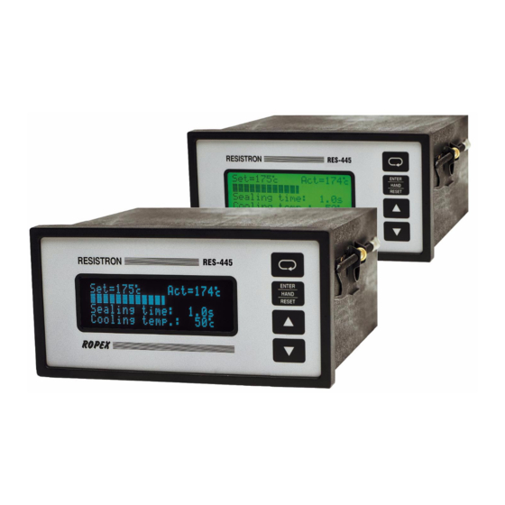
RESISTRON
RES-445
Operating
Instructions
Important features
•
Microprocessor technology
•
LC display (green), 4 lines, 20 characters, (multilingual)
Alternatively: VF display (blue), 4 lines, 20 characters, (multilingual)
•
Automatic zero calibration (AUTOCAL)
•
Automatic optimization (AUTOTUNE)
•
Automatic configuration of the secondary voltage and current ranges
(AUTORANGE, as of software revision 100)
•
Automatic phase angle compensation (AUTOCOMP, as of software revision 100)
•
Automatic frequency adjustment
•
Large current and voltage range
•
Booster connection as standard
•
Heatsealing band alloy and temperature range selectable
•
Time control, heatsealing time and cooling time settable
•
Preheating
•
Configurable relay output, e.g. "end of cycle"
•
Time or temperature-controlled cooling phase
•
Signal output for "Temperature OK"
•
0...10VDC analog input for set point selection, electrically isolated
•
0...10VDC analog output for ACTUAL temperature, electrically isolated
•
24VDC control inputs for AUTOCAL, PREHEAT and RESET, electrically isolated
•
Alarm function with fault diagnosis
Identical design to and compatible with RES-225
Industrie-Elektronik GmbH
Gansäcker 21
D-74321-Bietigheim-Bissingen (Germany)
GB
Tel: +49/(0)7142/7776-0
Fax: +49/(0)7142/7776-19
E-Mail:
info@ropex.de
Internet:
www.ropex.de
Data subject to change
Advertisement
Chapters
Table of Contents

Related Manuals for Ropex RES-225


Summary of Contents for Ropex RES-225
- Page 1 0…10VDC analog output for ACTUAL temperature, electrically isolated • 24VDC control inputs for AUTOCAL, PREHEAT and RESET, electrically isolated • Alarm function with fault diagnosis Identical design to and compatible with RES-225 Industrie-Elektronik GmbH Tel: +49/(0)7142/7776-0 E-Mail: info@ropex.de Gansäcker 21...
-
Page 2: Table Of Contents
Contents Safety and warning notes ....4 Controller functions ....27 Use . - Page 3 Maintenance ......67 How to order ..... . . 68 Index .
-
Page 4: Safety And Warning Notes
The resistance of the heatsealing band which is used must have a positive minimum Only the original ROPEX PEX-W2 or PEX-W3 temperature coefficient in order to guarantee current transformer may be used. Other trouble-free... -
Page 5: Line Filter
DIN EN 61010-1 Safety provisions for electrical (VDE 0411-1) measuring, control and laboratory The use of an original ROPEX line filter is mandatory in devices (low voltage directive). order to comply with the standards and provisions Overvoltage category III, pollution mentioned in section 1.7 "Standards / CE marking"... -
Page 6: Principle Of Operation
Principle of operation • etc. • Increased machine capacity The use of RESISTRON temperature controllers • Extended life of the heatsealing bands and teflon coatings results in: • Simple operation and control of the sealing process • Repeatable quality of the heatseals under any con- ditions Principle of operation The resistance of the heatsealing band, which is tem-... -
Page 7: Description Of The Controller
Description of the controller Description of the controller microprocessor technology endows The process data is represented on an LC display with RESISTRON temperature controller RES-445 with pre- 4 lines and 20 characters. Devices with a VF display viously unattainable capabilities: are available as an option. - Page 8 Designed according to VDE 0570/EN 61558 with a one-section bobbin. Optimized for impulse operation with RESISTRON temperature controllers. Specified according to the heatsealing application ( ROPEX Application Report). Communication interface CI-USB-1 Interface for connecting a RESISTRON temperature controller with diagnostic inter- face (DIAG) to the PC (USB port).
-
Page 9: Modifications (Mods)
Accessories and modifications Lockable door TUER-S/K-1 Transparent door (with lock) for mounting on the bezel of the controller. The display is clearly legible at all times. The keyboard can only be operated, however, by autho- rized persons in possession of a key. Measurement cable UML-1 Twisted measurement cable for the U voltage measurement. -
Page 10: Technical Data
Technical data Technical data Type of construction Housing for front panel mounting Dimensions (W x H): 144 x 72mm; depth: 161mm (incl. terminals) Line voltage All controller manufactured as of January 2006 (as of software revision 100): 115VAC version: 110VAC -15%…120VAC +10% (equivalent to 94…132VAC) 230VAC version: 220VAC -15%…240VAC +10% (equivalent to 187…264VAC) 400VAC version: 380VAC -15%…415VAC +10% (equivalent to 323…456VAC) All controllers manufactured as of January 2004 up to December 2005... - Page 11 Technical data Analog output 0…10VDC, Imax = 5mA (actual value) Equivalent to 0…300°C or 0…500°C Terminals 20+24 Electrically isolated Accuracy: ±1% add. 50mV Digital logic levels LOW (0V): 0…2VDC Terminals 3, 4, 22, 25, HIGH (24VDC): 12…30VDC (max. current input 6mA) Electrically isolated, reverse polarity-protected START with contact Switching threshold: 3.5VDC, U...
-
Page 12: Dimensions/Front Panel Cutout
Dimensions/front panel cutout Dimensions/front panel cutout panel cutout outline dimensions front frame ±0.2 ±0.2 x 68 rubber seal mounting clamp terminal wires terminal blocks terminal blocks front panel terminal wires front frame DIP-switch to select U , I Page 12 RES-445... -
Page 13: Installation
Kap. 8.3 „Power supply“ auf Seite 15, Kap. 8.6 „Wiring diagram (standard)“ auf Seite 17 and the Installation procedure ROPEX Application Report. The information pro- vided in Kap. 8.2 „Installation steps“ auf Seite 14 Proceed as follows to install the RESISTRON tempera- must be heeded additionally. -
Page 14: Installation Steps
Installation Installation steps Use heatseal bands with suitable temperature coefficient Heatseal element push-on with coppered ends connectors Heatsealing band R= f (T) No additional Connect U measuring resistance wires directly to in secondary Note heatsealing band ends circuit number Sufficient wire of turns Twisted cross-section... -
Page 15: Power Supply
Use transformers with a one section bobbin. The power, duty cycle and voltage values must be deter- SEC. mined individually according to the application ( ROPEX Application Report and "Accessories" leaflet for impulse transformers). Wiring The wire cross-sections depend on the application (... -
Page 16: Line Filter
CE mark. The wiring instructions contained in section 8.3 "Power ROPEX line filters are specially optimized for use in supply" on page 15 must be observed. RESISTRON control loops. Providing that they are... -
Page 17: Wiring Diagram (Standard)
Installation Wiring diagram (standard) Line filter LF-xx480 RES-445 LINE (also with MOD 01) RELAY K1 100VDC/1.5A 240VAC/1.5A 2x 47nF/560R ALARM OUTPUT max. 50V/0.2A Contact closed or prim. opened by ALARM (see configuration) Impulse transformer sec. PREHEAT (CH1) Heat- with 24VDC signal sealing band twisted... -
Page 18: Wiring Diagram With Booster Connection
Installation Wiring diagram with booster connection Line filter LF-xx480 RES-445 LINE (also with MOD 01) Booster RELAY K1 100VDC/1.5A 240VAC/1.5A 2x 47nF/560R ALARM OUTPUT max. 50V/0.2A Contact closed or prim. opened by ALARM (see configuration) Impulse transformer sec. PREHEAT (CH1) Heat- with 24VDC signal sealing... -
Page 19: Startup And Operation
(on rear of controller) Nameplate Clips Display Rear view of the controller As of software revision 100: Printed wiring diagram ROPEX 19 20 21 22 23 24 25 26 16 17 18 E6014431 19 20 21 22 23 24 25 26 SEC. PRIM. -
Page 20: Controller Configuration
Automatic configuration (AUTORANGE) You can find the exact configuration of the (as of software revision 100) DIP switches in the ROPEX Application Report calculated for your particular application. The secondary voltage and current ranges are auto- matically configured by the automatic calibration func-... - Page 21 Please refer to section 11 "Factory settings" on PEX-W2/W3 current transformer must have two turns page 65 for more information about the factory settings. ( ROPEX Application Report). If the controller settings are unknown when it is started up for the first time, the factory set- tings must be restored in order to prevent malfunc- tions.
-
Page 22: Relay K1
2. Temperature coefficient 1100ppm side the tolerance band, relay K1 is deactivated (see (Factory setting) graph below). (e.g. Alloy-20) 3. Temperature coefficient 1400ppm (e.g. ROPEX CIRUS system) Actual value Set+ 4. Temperature coefficient 1700ppm upper (e.g. ROPEX CIRUS system) 5. - Page 23 Startup and operation 3. "Active if Tact = Tset", with latch function The "Output 1" signal is available at terminals 20+21 as (as of software revision 100) a digital control signal. Relay K1 is closed if the actual value is inside the specified temperature tolerance band (steps 207, +24VDC RES-445...
- Page 24 Startup and operation As of software revision 100: and causes" on page 64). If a heatsealing cycle is in If time control (timer function) is deactivated, the same progress, it is immediately interrupted. configuration options are available for "Output 1" as for relay K1 (...
-
Page 25: Heatsealing Band
Startup and operation ximately 2…3%. However, this at first glance slight Actual value resistance change results in a zero point error of 20…30°C. The zero point must therefore be corrected after a few heating cycles ( chap. 9.4.2 „Burning in the heatsealing band“, page 25). -
Page 26: Startup Procedure
DIP switches on the controller are erro message indicates error codes 104…106, 211. indicated in the ROPEX Application report and In this case the controller configuration is incorrect depend on the heatsealing band (section 9.3 "Con- (... -
Page 27: Controller Functions
Return to home position ENTER HAND RESET "ENTER" key ENTER function: Save values ROPEX Manual mode HAND function: RESET function: Reset after alarm "UP" and "DOWN" keys for setting values Press (< 2 sec.): Slow change Hold (> 2 sec.): Fast change... -
Page 28: Display
Controller functions 10.2 Display This message also includes details of the software ver- sion. 10.2.1 Power-up message A power-up message appears on the display for appro- ximately 2 seconds when the controller is switched on. Company name (optional: customer-specific) Software ID number Controller type (RES-445) 10.2.2 Display in home position a digital value and the ACTUAL temperature as a digital... -
Page 29: Navigation In The Menus
Controller functions 10.2.4 Error messages immediately in the form of an error message ( Kap. 10.25 „System monitoring/alarm output“ auf The fault diagnosis function of the controller is always Seite 59). active. If a fault is detected, it is indicated on the display Alarm indication Fault description and error code... - Page 30 Controller functions 10.3.2 Navigation in menus with a fault can then activate the "AUTOCAL" function by pressing the "ENTER" key ( section 10.9 "Automatic zero cali- If an alarm is signaled, the controller switches to the bration (AUTOCAL)" on page 45). Alarm menu.
-
Page 31: Menu Structure
Controller functions 10.4 Menu structure Settings Configuration Power-up message Home position Language 1) Time control: ON 2) Time control: OFF Factory settings 101 Heatsealing temp. 3) AUTOCOMP: OFF 4) AUTOCOMP: ON Alloy 102 Preheating temp. 5) TCR variable 6) TCR not variable 204 Temp. - Page 32 Controller functions Configuration Continued from previous page Heatup timeout 220 Meas. imp. length Autocomp "Output 1" 225 Temperature unit Back to home position Page 32 RES-445...
-
Page 33: Two-Digit Numbering System
Controller functions 10.5 Two-digit numbering system revision 027. Three-digit numbers were introduced in software revision 100 to improve the clarity of the menu up to software revision 027 structure. The table below compares the two numbering systems: A system of one and two-digit numbers was used for the Settings and Configuration menus up to software Numbering Numbering... -
Page 34: Menu Steps
Controller functions 10.6 Menu steps Name Description Setting range Home position The specified set value and the current actual value are displayed in digital form. The actual value is also represented as a dynamic bar. If time control (step 209 [26]) is active, the heatse- aling time and the cooling value are also displayed. - Page 35 Controller functions Name Description Setting range Cooling value The cooling value can be specified here according to the cooling mode (absolute, relative, time) selected with step 210 [27]. • Absolute: The cycle ends if the "cooling temper- 50°C to maximum tempe- ature"...
- Page 36 In addition, as of software revision 100: The "UP" and "DOWN" keys can be used to select whether • The controller should be reset to the ROPEX fac- tory settings • The current configuration should be specified as the default setting •...
- Page 37 Controller functions Name Description Setting range Alloy/range This step in the Configuration menu is (Availability depends on available up to software revision 027 only. software revision) TCR 410ppm, 300°C Various heatsealing band alloys and temperature TCR 460ppm, 300°C ranges can be selected here. TCR 510ppm, 300°C The corresponding characteristic for the controller TCR 570ppm, 300°C...
- Page 38 Controller functions Name Description Setting range Set point reached As of software revision 100: -5K…-99K [24] (low limit) If the actual value is greater than the switching threshold specified here and less than the threshold set with step 208, "Output 1" and/or relay K1 can be activated depending on the configuration (step 212 or 222).
- Page 39 Controller functions Name Description Setting range Cooling mode The end of the cooling-down phase (end of cycle) [27] can be configured by specifying the required cooling mode. • Absolute: The cycle ends if the actual value falls Absolute (in °C) below the cooling temperature set here.
- Page 40 Controller functions Name Description Setting range • In addition, as of software revision 100: Relay K1 active if Tact = K1 is energized if the actual value is inside the Tset, with latch function specified temperature tolerance band (steps 207, 208). The relay remains energized at the end of the heatsealing cycle and is not deen- ergized again until the next "START"...
- Page 41 Controller functions Name Description Setting range Alarm relay This menu step permits the switching characteri- [31] stics of the alarm relay to be configured. • Normal: The alarm relay output (terminals 5+6) Normal operates as an NO contact in the event of a fault. •...
-
Page 42: Start (Heat)
Controller functions Name Description Setting range • Output 1 is energized if the actual value is inside "Output 1" active if Tact = the specified temperature tolerance band Tset, with latch function (steps 207, 208). The relay remains energized at the end of the heatsealing cycle and is not deen- ergized again until the next "START"... -
Page 43: Temperature Setting
Controller functions 10.7 Temperature setting (set point aling band will not be heated up when the "START" signal is activated or the "HAND" key is pressed. selection) The set heatsealing temperature is displayed in the main menu once it has been entered. The heatsealing temperature can be set on the RES-445 controller in three ways: If the heatsealing temperature is specified via... -
Page 44: Output
An indicating instrument can be connected to this output in order to visualize the temperature of the heat- sealing band. The characteristics of the ROPEX ATR-x temperature meter (size, scaling, dynamic response) are ideally suited to this application ( section 5 "Accessories and modifications"... -
Page 45: Automatic Zero Calibration
Controller functions It not only facilitates SET-ACTUAL comparisons, but • By means of a 24VDC signal at terminals 20+25. also enables other criteria such as the heating rate, set point reached within the specified time, cooling of the 24VDC RES-445 heatsealing band etc. -
Page 46: Start" Signal (Heat)
Controller functions You should always wait for the heatsealing parameter. The "START" signal must be deactivated band and the bar to cool down (to ambient again before the next timeout is activated. temperature) before activating the "AUTOCAL" Pressing the "HAND" key while the display is in the function. -
Page 47: Preheat" Signal
Controller functions "Fault areas and causes" on page 64). The heatsealing • By means of a control contact at terminals 2+19 band is likewise not heated. If a "PREHEAT" signal is used, it is deactivated inter- max. RES-445 nally during the heating and control process. The heat- sealing band is not returned to the set preheating tem- perature until the "PREHEAT"... -
Page 48: Reset" Signal
Controller functions The ACTUAL temperature shows whether the heatse- • An error message is reset if one is present aling band is heated up to the preheating temperature correctly, providing the display is in the home position. 24VDC RES-445 RESET Please note the following if the "PREHEAT"... -
Page 49: Hold Mode
Controller functions The cycle counter is reset to 0 if the "ENTER" key is The various hold modes are shown below: pressed or if the maximum count of 999.999.999 cycles START is exceeded. signal 24VDC 10.14 Hold mode The behavior of the digital indication of the ACTUAL ACTUAL temperature in the home position can be changed with temp. -
Page 50: Measuring Impulse Duration (As Of Software Revision 026)
It may be necessary to compensate the phase angle displacement between the U and I measuring signals in certain heatsealing applications ( ROPEX Function AUTOCOMP Application Report). The "AUTOCOMP" function is pro- vided for this purpose. It can be parameterized with... -
Page 51: Temperature Unit Celsius / Fahrenheit (As Of Software Revision 106)
Controller functions 10.18 Temperature unit You can still display all steps, values and parameters even if the Configuration menu is Celsius / Fahrenheit disabled. You are no longer allowed to enter or (as of software revision 106) change values, however. As of software revision 106 the unit for the temperature As of software revision 103 the language in indication and value selection can be switched between... -
Page 52: Undervoltage Detection
20+24). The alarm relay in controllers with a higher software The ROPEX visualization software is described in a revision number is not switched if an undervoltage con- separate document. dition occurs. The standby mode is indicated by 0…3°C (corresponds to app. -
Page 53: Time Control (Timer Function)
Controller functions 10.24 Time control (timer function) with the "HAND" key on the controller. The timeout of the internal time control cannot be started with this key. 10.24.1 Activation and indication START The settings described here are only allowed signal to be entered by technically trained persons. - Page 54 Controller functions The active cooling phase is subsequently marked with The starting delay can be set in the range from 0 to the direction arrow at the end of the heating phase. 9.9s. A delay of 0s is defined as the factory setting. In this case, the heating process begins as soon as the "START"...
- Page 55 Controller functions SET temperature = 180°C, cooling value = 60% menu. All settings entered with menu step 105 [5] Cooling phase ends when ACTUAL are overwritten if step 210 [27] is changed subse- temperature 108°C quently. 3. "Time" The possible settings are as follows: The cooling phase ends after a specified time in 1.
- Page 56 Controller functions These two alternatives are shown below: (Software revision 010 or higher) The normally open contact of relay K1 closes at the START end of the heating phase and opens again at the signal end of the cooling phase. 24VDC This configuration permits air cooling to be activated with relay K1 during the cooling phase, for instance.
- Page 57 Controller functions 10.24.8 “Output 1“/ 6. "Active if Tact = Tset" (This setting is possible as of software „Temperature OK“ signal revision 100) (with time control) Relay K1 is activated if the actual value is inside the specified temperature tolerance band (steps 207, On controllers up to software revision 027, 208).
- Page 58 Controller functions 10.24.9 Preheating (with time control) never reached, i.e. the internal timeout does not elapse. If time control is active, the preheating temperature If the cooling temperature is required to be lower than ( section 10.11 ""PREHEAT" signal (preheating)" on the preheating temperature, the "PREHEAT"...
-
Page 59: System Monitoring/Alarm Output
Controller functions 10.25 System monitoring/alarm output The timing sequence can be represented as follows: START signal (foot switch) To increase operating safety and to avoid faulty heatse- aling, the controller incorporates special hardware and software features that facilitate selective fault detection and diagnosis. -
Page 60: Error Messages
( section 10.12 The error codes described below can also be displayed ""RESET" signal" on page 48) or by switching the in the ROPEX visualization software ( section 10.22 controller off and then on again. "Diagnostic interface/visualization software (as of soft- ware revision 100)"... - Page 61 Controller functions RES-445 Page 61...
- Page 62 Controller functions Page 62 RES-445...
- Page 63 Controller functions RES-445 Page 63...
-
Page 64: Fault Areas And Causes
Controller functions 10.27 Fault areas and causes Temperature controller HARDWARE The table below explains the possible fault causes. Fault area Explanation Possible causes Load circuit interrupted after U - Wire break, heatsealing band break - Contacting to heatsealing band defective pickoff point ... -
Page 65: Factory Settings
Factory settings Fault area Explanation Possible causes - Up to software revision 027: DIP switches 4+5 configured incorrectly (I range) signal incorrect - As of software revision 100: I outside permissible range from 30…500A Turns through PEX-W2/W3 cur- - Check number of turns (two or more turns required for rent transformer incorrect currents <... - Page 66 Factory settings Configuration menu No. 201 [20] Language German This selection is NOT changed if the factory settings are restored with step 202 [21] in the Config. menu. No. 203, 204 [22] Alloy/range: Alloy-20/max. 300°C No. 206 [23] Maximum temperature: 300°C No.
-
Page 67: Customer Settings (As Of Software Revision 100)
Settings and Configura- Step 203 then appears on the display. tion menus as "customer settings". These "cus- tomer settings" are independent of the Ropex The language which is selected with step 201 settings. Machine-specific settings can be stored in in the Configuration menu remains set even if the controller in this way. -
Page 68: Impulse Transformer
Line filter LF- . . 480 06: Continuous current 6A, 480VAC, Art. No. 885500 35: Continuous current 35A, 480VAC, Art. No. 885506 Impulse transformer See ROPEX Application Report for design and ordering information Communication interface CI-USB-1 Art. No. 885650 Temp. meter ATR- . - Page 69 How to order Booster B- . . . 400 075: Max. pulse load 75A, 400VAC, Art. No. 885301 100: Max. pulse load 100A, 400VAC, Art. No. 885304 For more accessories: "Accessories" leaflet RES-445 Page 69...
- Page 70 Index Index Front cover Accessories Actual value output Adapter for top hat rail mounting HEAT Additional relay K1 Heatsealing band type Alarm output Heatup timeout Alarm relay Hold mode Alloy Ambient temperature Analog temperature meter Impulse heatsealing method Application Impulse transformer Application Report Installation AUTOCAL...
- Page 71 Index Set point selection Temperature unit Standby mode Time control "START" signal Timer function System diagnostics Transformer System monitoring Type of construction Undervoltage detection Temperature coefficient Temperature control Temperature diagnosis View of controller Temperature indication Visualization software Temperature meter Temperature OK Temperature OK signal Wiring Temperature range...
Need help?
Do you have a question about the RES-225 and is the answer not in the manual?
Questions and answers