Table of Contents
Advertisement
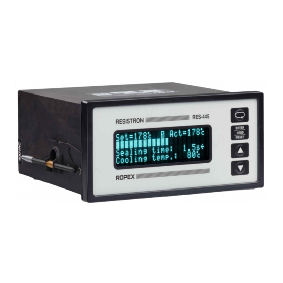
RESISTRON
RES-445
Operating
Instructions
Important features
•
Microprocessor technology
•
LC display (green), 4 lines, 20 characters, (multilingual)
Alternatively:
VF display (blue), 4 lines, 20 characters, (multilingual)
•
Automatic zero calibration (AUTOCAL)
•
Automatic optimization (AUTOTUNE)
•
Automatic frequency adjustment
•
Large current and voltage range
•
Booster connection as standard
•
Heatsealing band alloy and temperature range selectable
•
Time control, heatsealing time and cooling time settable
•
Preheating
•
Configurable relay output, e.g. "end of cycle"
•
Time or temperature-controlled cooling phase
•
Signal output for "Temperature OK"
•
0...10VDC analog input for set point selection, electrically isolated
•
0...10VDC analog output for ACTUAL temperature, electrically isolated
•
24VDC control inputs for AUTOCAL, PREHEAT and RESET, electrically isolated
•
Alarm function with fault diagnosis
Identical design to and compatible with RES-225,
Industrie-Elektronik GmbH
Gansäcker 21
D-74321-Bietigheim-Bissingen (Germany)
GB
Tel: +49/(0)7142/7776-0
Fax: +49/(0)7142/7776-19
E-Mail:
info@ropex.de
Internet:
www.ropex.de
Data subject to change
Advertisement
Table of Contents

Related Manuals for Ropex RES-445

Summary of Contents for Ropex RES-445
- Page 1 RESISTRON RES-445 Operating Instructions Important features • Microprocessor technology • LC display (green), 4 lines, 20 characters, (multilingual) Alternatively: VF display (blue), 4 lines, 20 characters, (multilingual) • Automatic zero calibration (AUTOCAL) • Automatic optimization (AUTOTUNE) • Automatic frequency adjustment •...
-
Page 2: Table Of Contents
Index ......55 Startup procedure ....21 Page 2 RES-445... -
Page 3: Safety And Warning Notes
The resistance of the heatsealing band which is used must have a positive minimum Only the original ROPEX PEX-W2 current temperature coefficient in order to guarantee transformer may be used. Other transformers trouble-free... -
Page 4: Line Filter
Line filter DIN EN 61010-1 Safety provisions for electrical The use of an original ROPEX line filter is mandatory in (VDE 0411-1) measuring, control and laboratory order to comply with the standards and provisions devices (low voltage directive). -
Page 5: Principle Of Operation
Heatsealing band R = f (T) RESISTRON controller Actual value Current R=f(T) transformer Indicators Start sec. controls prim. Set point bus interface Impulse transformer LINE RES-445 Page 5... -
Page 6: Description Of The Controller
A wide range of compatible accessories and peripheral devices are available for the RESISTRON temperature controller RES-445. They allow it to be optimally The products described below are only a few of the adapted to your specific heatsealing application and to wide range of accessories available for RESISTRON your plant's design and operating philosophy. - Page 7 Also facilitates applications in the food technology sector (GMP). Adapter for top hat rail mounting, HS-Adapter-01 For mounting the RESISTRON temperature controller RES-445 on a top hat rail (DIN TS35). Allows the controller to be installed in the electrical cabinet, for instance, where it is only accessible to authorized persons.
-
Page 8: Modifications (Mods)
Modifications (MODs) MOD 01 Amplifier secondary voltages Owing to its universal design, the RESISTRON = 0.25…16VAC). This modification is necessary, temperature controller RES-445 is suitable for a very example, very short low-resistance wide range of heatsealing applications. heatsealing bands. Modifications (MOD) are available for the RESISTRON... -
Page 9: Technical Data
= 30VDC, I = 50mA for "Temp. OK" signal < 2V (saturation voltage) Terminals 20+21 Transistor conductive if the temperature is inside the tolerance band. Alarm relay Contact, potential-free, U = 50VDC, I = 0.2A Terminals 5+6 RES-445 Page 9... - Page 10 Installed in front panel cutout with (W x H) 138 x 68 Fastened with clips Weight Approx. 1.0kg (incl. connector plug-in parts) Housing material Black plastic, type Noryl SE1 GFN2 Connecting cable Rigid or flexible; 0.2…2.5mm² (AWG 24…12) Type / cross-sections Plug-in connectors Page 10 RES-445...
-
Page 11: Dimensions/Front Panel Cutout
Dimensions/front panel cutout Dimensions/front panel cutout panel cutout outline dimensions front frame ±0.2 ±0.2 x 68 rubber seal mounting clamp terminal wires terminal blocks terminal blocks front panel terminal wires front frame DIP-switch to select U , I RES-445 Page 11... -
Page 12: Installation
Kap. 8.2 „Installation steps“ auf Seite 13 Proceed as follows to install the RESISTRON must be heeded additionally. temperature controller RES-445: 1. Switch off the line voltage and verify that all circuits Check the tightness of all the system are deenergized. -
Page 13: Installation Steps
I R U (prim.) U (sec.) Line Line filter Avoid long LF-xx480 cables OPTION: Temperature meter Impulse ATR-x transformer Dimension transformer correctly Controller - Secondary voltage Note - Power polarity - Duty cycle Configure DIP switches correctly RES-445 Page 13... -
Page 14: Power Supply
Use transformers with a one-section bobbin. The power, duty cycle and voltage values must be determined individually according to the application SEC. (! ROPEX Application Report and "Accessories" leaflet for impulse transformers). Wiring The wire cross-sections depend on the application (! ROPEX Application Report). -
Page 15: Line Filter
CE mark. The wiring instructions contained in section 8.3 "Power ROPEX line filters are specially optimized for use in supply" on page 14 must be observed. RESISTRON control loops. Providing they are installed... -
Page 16: Wiring Diagram (Standard)
Installation Wiring diagram (standard) Line filter LF-xx480 RES-445 LINE (also with MOD 01) RELAY K1 100VDC/1.5A 240VAC/1.5A 2x 47nF/560R ALARM OUTPUT max. 50V/0.2A Contact closed or prim. opened by ALARM (see configuration) Impulse transformer sec. PREHEAT (CH1) Heat- with 24VDC signal... -
Page 17: Wiring Diagram With Booster Connection
Installation Wiring diagram with booster connection Line filter LF-xx480 RES-445 LINE (also with MOD 01) Booster RELAY K1 100VDC/1.5A 240VAC/1.5A 2x 47nF/560R ALARM OUTPUT max. 50V/0.2A Contact closed or prim. opened by ALARM (see configuration) Impulse transformer sec. PREHEAT (CH1) -
Page 18: Startup And Operation
The possible controller configurations are explained in the following sections. Proceed as described in The controller must be switched off in order Kap. 9.5.1 „Initial startup“ auf Seite 21 to start up the to configure the DIP switches. controller for the first time. Page 18 RES-445... - Page 19 Set the DIP switches for matching the secondary You can find the exact configuration of the voltage U and the secondary current I to the correct DIP switches in the ROPEX Application position for your application. Report calculated for your particular application. Factory settings Rear view...
-
Page 20: Heatsealing Band
General The heatsealing band is a key component in the control loop, since it is both a heating element and a sensor. The geometry of the heatsealing band is too complex to (•) Factory setting (••)Factory setting Page 20 RES-445... -
Page 21: Startup Procedure
3. The settings of the DIP switches on the controller (display in home position) to heat for approximately depend on the ROPEX Application Report and the 1 second. After recooling, the controller usually heatsealing band that is used (Kap. 9.3 „Controller indicates a value less than 20°C. - Page 22 104…106, 211. In this case the controller configuration is incorrect (! Kap. 9.3 „Controller configuration“ auf Seite 18 DISPLAY ACTION and ROPEX Application Report). Repeat the zero Main menu Go to 8 point calibration after the controller has been configured correctly.
-
Page 23: Controller Functions
This message also includes details of the software version. 10.2.1 Power-up message A power-up message appears on the display for approximately 2 seconds when the controller is Company name (optional: customer-specific) Software ID number Controller type (RES-445) RES-445 Page 23... - Page 24 (! Kap. 10.20 „System monitoring/alarm output“ auf The fault diagnosis function of the controller is always Seite 48). active. If a fault is detected, it is indicated on the display Alarm indication Fault description and error code Prompt to press "RESET" key Page 24 RES-445...
-
Page 25: Navigation In The Menus
30s from "AUTOCAL" or return to the home position from anywhere in the menu "Alarm". Settings Configuration Home position Language >2s >2s automatically after 30s <2s <2s Heatsealing temp. Factory settings >2s >2s automatically automatically after 30s after 30s RES-445 Page 25... - Page 26 "MENU" key (<2s). You Alarm ENTER Alarm Language HAND RESET >2s >2s automatically Home position after 30s <2s <2s ENTER Autocal? Factory settings HAND RESET >2s Autocal automatically after 30s End of Autocal Page 26 RES-445...
-
Page 27: Menu Structure
1) Time control ON Hold mode 2) Time control OFF Cooling mode Autocal? 28 Start of sealing time Autocal Relay K1 function Cycles Fault Alarm relay Alarm 32 Meas. imp. length MOD 1 only Autocal? Analog output Autocal RES-445 Page 27... -
Page 28: Menu Steps
The length of the heatsealing pulse can be set with 0…99.9s, EXT the "UP" and "DOWN" keys. The specified heatsealing time is indicated in the home position. This function can only be selected if time control (step 26) is active. Page 28 RES-445... - Page 29 13 to 0. When the controller has been calibrated successfully, the display switches back directly to the home position. If the controller cannot be calibrated, the AUTOCAL function is aborted and an error message is displayed instead. RES-445 Page 29...
- Page 30 25, the "Temperature OK" output is activated. The value is entered in Kelvins (K) and subtracted from the set point in order to calculate the switching threshold. Page 30 RES-445...
- Page 31 (step 4) should begin as soon as the start when heating starts signal is applied or when 95% of the set point is reached. Heatsealing time starts This function can only be selected if time control when temperature (step 26) is active. reached RES-445 Page 31...
- Page 32 Analog output This menu step determines whether the current Real temperature, actual value or a 10V reference voltage is output at 10V reference the actual value output (terminal 24). (This setting is possible as of SW revision 017) Page 32 RES-445...
-
Page 33: Temperature Setting
"START" signal is activated or the "HAND" key is The heatsealing temperature can be set on the pressed. RES-445 controller in three ways: The set heatsealing temperature is displayed in the • By means of the setting in menu step 1. -
Page 34: Temperature Indication/Actual Value
The heating and control process can thus be monitored at any time. In addition, the RES-445 controller outputs an electrically isolated, analog 0…10VDC signal, which is 20°C proportional to the real ACTUAL temperature, at 9 10 terminals 20+24. -
Page 35: Automatic Zero Calibration
By means of a 24VDC signal at terminals 20+25. modifications“ auf Seite 6). It not only facilitates SET-ACTUAL comparisons, but 24VDC RES-445 also enables other criteria such as the heating rate, set AUTOCAL point reached within the specified time, cooling of the heatsealing band etc. -
Page 36: Start" Signal (Heat)
0.1K/second. This is additionally indicated with step 7 in the Settings menu by the message 24VDC "Heatsealing band still hot! Please wait...". RES-445 START As of software revision 012, this message is also (HEAT) displayed if the controller cannot be calibrated when max. -
Page 37: Preheat" Signal
By means of a control contact at terminals 2+19 likewise not heated. If a "PREHEAT" signal is used, it is deactivated max. RES-445 internally during the heating and control process. The heatsealing band is not returned to the set preheating temperature until the "PREHEAT" signal is activated... -
Page 38: Reset" Signal
ACTUAL 10.11 "RESET" signal temperature is within a settable tolerance band ("OK" window) on either side of the set temperature. The The RESISTRON temperature controller RES-445 can ∆ϑ ∆ϑ lower ( ) and upper ( ) limits of the be reset by means of an external "RESET"... -
Page 39: Cycle Counter
6 in the Settings menu: The "Temperature OK" signal is available at terminals 20+21 as a digital control signal. +24VDC RES-445 The following settings are possible: 50mA 1. "OFF" (•) If the main menu is visible on the display, the real ACTUAL temperature is always indicated. - Page 40 The various hold modes are shown below: START signal 24VDC ACTUAL temp. ACTUAL indication Hold OFF Hold ON Hold Hold Hold 2 s Hold Hold End of heating phase Page 40 RES-445...
-
Page 41: Disabling The Configuration Menu
If the display is in the home position, the brightness of monitor must be connected to prevent defective the VF display (blue) can be set in 4 steps (25%, 50%, heatseals as a result of low line voltage. RES-445 Page 41... -
Page 42: Booster Connection
10.18 Booster connection activated - the timeout is interrupted. The RES-445 controller has a connection for an If time control is on, activating the "START" signal starts external switching amplifier (booster) as standard. This the internally parameterized timeout. This timeout... - Page 43 The heatsealing time is controlled by the "START" the Settings menu, e.g. in order to bridge the closing signal (24VDC signal applied to terminals 3+4 or time of the heatsealing bars. contact applied to terminals 2+7). The duration of the RES-445 Page 43...
- Page 44 Absolute 10.19.4 Setting the cooling mode Various criteria for the end of the cooling phase can be specified with step 27 in the Configuration menu of the RES-445 controller: = Cooling phase as Relative % of set point = Cooling phase in s.
- Page 45 Once again, the heating process starts as soon as soon as the "START" signal is activated and the set starting delay elapses (! Settings menu, remains closed until the end of the parameterized (•) Factory setting timeout (i.e. until the end of the cooling phase). RES-445 Page 45...
- Page 46 500ms. If a "START" signal is activated while relay K1 is still closed, the relay opens again immediately. When temperature reached While cooling End-of- 500ms cycle impulse (•) Factory setting Page 46 RES-445...
- Page 47 6. The normally open contact of relay K1 opens again is then energized and the sealing jaws are closed. at the end of the cooling phase. The sealing jaws heatsealing time = 1s) begins are also opened again. simultaneously. 7. End of the heatsealing process. RES-445 Page 47...
-
Page 48: System Monitoring/Alarm Output
5 (Cooling value) Cooling temperature jumps back and forth at 1Hz between the voltage value = 80°C that corresponds to this error and the end of the scale (10VDC, i.e. 300°C or 500°C). If the "START" signal is Page 48 RES-445... -
Page 49: Error Messages
An alarm can be reset by pressing the quickly and efficiently. "RESET" key, by activating the "RESET" signal at terminals 20+26 (! Kap. 10.11 „"RESET" signal“ auf Seite 38) or by switching the controller off and then on again. RES-445 Page 49... - Page 50 Controller functions Page 50 RES-445...
-
Page 51: Fault Areas And Causes
- DIP switches 4 + 5 configured incorrectly (I range) Turns through PEX-W2 current - Check number of turns (two or more turns required for transformer incorrect currents < 30A) & Internal controller fault - Hardware fault (replace controller) RES-445 Page 51... -
Page 52: Factory Settings
Factory settings Factory settings The RESISTRON temperature controller RES-445 is configured in the factory as follows: DIP switches = 6…60VAC = 30…100A secondary voltage and current I DIP switches: 2 ON 1, 3, 4, 5 OFF Values in the Settings... -
Page 53: Maintenance
The controller requires no special maintenance. the impulse transformer – is recommended. Dust Regular inspection and/or tightening of the terminals – deposits on the controller can be removed with dry including the terminals for the winding connections on compressed air. RES-445 Page 53... -
Page 54: How To Order
Line filter LF- . . 480 06: Continuous current 6A, 480VAC, Art. No. 885500 35: Continuous current 35A, 480VAC, Art. No. 885506 Impulse transformer See ROPEX Application Report for design and ordering information Temp. meter ATR- . 3: 300°C range, Art. No. 882130 5: 500°C range, Art. -
Page 55: Index
Set point selection Standby mode "START" signal Factory settings System monitoring Fault areas Fault diagnosis Front cover Temperature coefficient Temperature control HEAT Temperature indication Heatsealing band type Temperature meter Hold mode Temperature OK Temperature OK signal Temperature range RES-445 Page 55... - Page 56 Index Temperature setting Time control View of controller Timer function Transformer Type of construction Wiring Wiring diagram Undervoltage detection Page 56 RES-445...
Need help?
Do you have a question about the RES-445 and is the answer not in the manual?
Questions and answers