Table of Contents
Advertisement
Quick Links
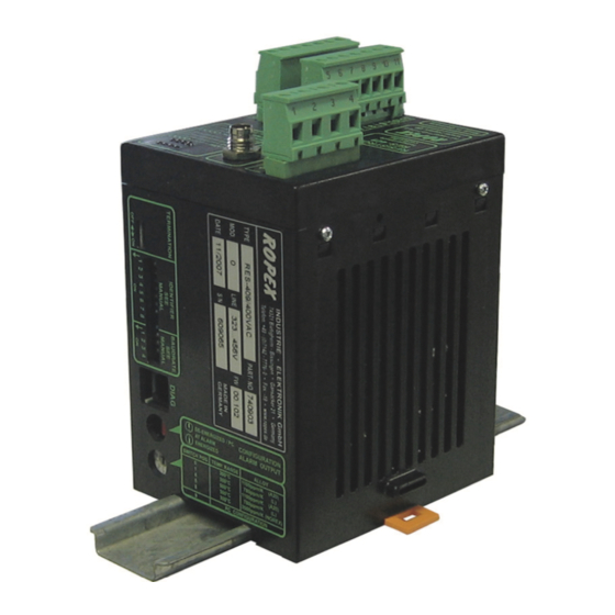
RESISTRON
RES-409
Operating
instructions
Important features
•
Microprocessor technology
•
Complete control via CAN-Bus interface (CAN 2.0A according ISO 11898)
Remark: CANopen is not supported
•
Automatic zero calibration (AUTOCAL)
•
Automatic optimization (AUTOTUNE)
•
Automatic configuration of the secondary voltage and current ranges
(AUTORANGE, as of February 2007)
•
Automatic phase angle compensation (AUTOCOMP, as of February 2007)
•
Automatic frequency adjustment
•
Large current and voltage range
•
0...10VDC analog output for ACTUAL temperature
•
Additional 24VDC control signals for START 0 (Set 0) and START 1 (Set 1)
(as of February 2007)
•
Alarm function with fault diagnosis
•
Heatsealing band alloy and temperature range selectable
•
Booster connection as standard (as of February 2007)
ROPEX Industrie-Elektronik GmbH
Adolf-Heim-Str. 4
74321 Bietigheim-Bissingen (Germany)
Tel.: +49 (0)7142-7776-0
Fax: +49 (0)7142-7776-211
E-Mail:
info@ropex.de
Internet:
https://ropex.de
Data subject to change
Advertisement
Table of Contents

Subscribe to Our Youtube Channel
Related Manuals for Ropex RESISTRON RES-409


Summary of Contents for Ropex RESISTRON RES-409
- Page 1 (as of February 2007) • Alarm function with fault diagnosis • Heatsealing band alloy and temperature range selectable • Booster connection as standard (as of February 2007) ROPEX Industrie-Elektronik GmbH Tel.: +49 (0)7142-7776-0 E-Mail: info@ropex.de Adolf-Heim-Str. 4 Fax: +49 (0)7142-7776-211 Internet: https://ropex.de...
-
Page 2: Table Of Contents
Contents General information ....3 Controller functions ....30 Copyright . -
Page 3: General Information
The temperature coefficient must be taken from the ROPEX application report and must be set accordingly. The use of incorrect alloys with a too low temperature coefficient and incorrect coding of the ®... -
Page 4: Impulse Transformer
The use of an original ROPEX line filter is mandatory in order to comply with the directives mentioned in section "DECLARATION OF CONFORMITY" on page 6. This device must be installed and connected according to the instructions contained in section "Power supply"... -
Page 5: Disposal
General information Disposal This device is subject to Directive 2012/19/EU concerning the reduction of the increasing amount of waste electrical and electronic equipment and the disposal of such waste in an environmentally sound way. To guarantee proper disposal and / or the recover of reusable material, please take the device to a designated municipal collection point and observe local regulations. - Page 6 We also wish to point out that the transformer which is used must be designed in accordance with VDE 0551/EN 61558 or UL 5058 for safety reasons. July 12, 2020 J. Kühner (CEO) ROPEX Industrie-Elektronik GmbH Adolf-Heim-Str. 4 74321 Bietigheim-Bissingen (Germany) Page 6...
-
Page 7: Application
Application Application ® This RESISTRON temperature controller is an integral part of the "Series 400", the outstanding feature of which is its microprocessor technology. All RESISTRON temperature controllers are used to control the temperature of heating elements (heatsealing bands, beaded bands, cutting wires, heatsealing blades, solder elements etc.), as required in a variety of heatsealing processes. -
Page 8: Description Of The Controller
Description of the controller the system components, in other words the heatsealing band, the impulse transformer, the wiring, the timing signals and the controller itself, are carefully compatible and interrelated. We will be pleased to contribute our many years of experience your towards optimizing heatsealing system. -
Page 9: Accessories And Modifications
Designed according to VDE 0570/EN 61558 with a one section bobbin. Optimized for impulse operation with RESISTRON temperature controllers. Specified according to the heatsealing application ( ROPEX Application Report). Communication interface CI-USB-1 Interface for connecting a RESISTRON temperature controller with diagnostic inter- face (DIAG) to the PC (USB port). -
Page 10: Modifications (Mods)
Accessories and modifications Booster B-xxx400 External switching amplifier, necessary for high primary currents (continuous current > 5A, pulsed current > 25A). Monitoring current transformer For detecting frame short-circuits on the heatsealing band. Used as an alternative to the standard PEX-W2/-W3 current transformer. Measurement cable UML-1 twisted measurement cable for the U -voltage measurement. -
Page 11: Technical Data
Technical data Technical data Type of construction Housing for installation in the electrical cabinet Snaps onto a standard top hat rail (DIN TS35 rail, 35 mm) acc. to DIN EN 50022 Dimensions: 90 x 75mm; height: 135mm (incl. terminals) Line voltage All controllers manufactured as of February 2007: 115VAC version: 110VAC -15%…120VAC +10% (equivalent to 94…132VAC) 230VAC version: 220VAC -15%…240VAC +10% (equivalent to 187…264VAC) - Page 12 The temperature range and temperature coefficient settings can also be specified range in the ROPEX visualization software ( section 10.12 "Diagnostic interface / visualization software (as of February 2007)" on page 50) in addition to using the rotary coding switch (see below) or the CAN interface: Temperature range: 200°C, 300°C, 400°C or 500°C...
- Page 13 Technical data Ambient +5…+45°C temperature Degree of protection IP20 Installation If several controllers are installed on one top hat rail (DIN TS35 rail), a clearance of at least 20mm should be allowed between them. The moving clip required for fastening must be facing down for mounting on a horizontal top hat rail.
-
Page 14: Dimensions
Dimensions Dimensions 75.0 90.0 Montage und Installation See also section 1 "General information" on page 3. Installation and startup may only be performed by technically trained, skilled persons who are familiar with the associated risks and warranty provisions. Installation procedure ®... - Page 15 4. Wire the system in accordance with the instructions in section 8.3 "Power supply" on page 17, section 8.6 "Wiring diagram (standard)" on page 20 and the ROPEX Application Report. The information provided in section 8.2 "Installation steps" on page 16 must be additionally heeded.
-
Page 16: Installation Steps
Montage und Installation Installation steps Use heatseal bands with suitable temperature coefficient Heatseal element push-on with coppered ends connectors Heatsealing band R= f (T) No additional Connect U measuring resistance wires directly to in secondary Note heatsealing band ends circuit number Sufficient wire of turns... -
Page 17: Power Supply
Connect core to ground. Use transformers with a one section bobbin. The power, duty cycle and voltage values must be deter- mined individually according to the application ( ROPEX SEC. Application Report and "Accessories" leaflet for impulse transformers). -
Page 18: Line Filter
ROPEX line filters are specially optimized for use in RESISTRON control loops. Providing that they are installed and wired correctly, they guarantee compliance with the EMC limit values. You can find the exact specification of the line filter in the ROPEX Application Report calculated for your particular heatsealing application. - Page 19 Montage und Installation 8.5.1 PEX-W4 terminal wires terminal block Snap-on for DIN-rail 35 x 7.5 mm or 35 x 15 mm (DIN EN 50022) 8.5.2 PEX-W5 Mounting on DIN-rail 35 x 7.5 mm or 35 x 15 mm (DIN EN 50022). Version 1 RES-409 Page 19...
-
Page 20: Wiring Diagram (Standard)
Montage und Installation Wiring diagram (standard) CAN bus Line filter LF-xx480 Plug assignment RES-409 (RES-409) LINE 3 = blue (also with MOD 01) 4 = black 1 = brown CAN bus Plug 1 CAN bus 3-pole Controller Bus GND electrically isolated CAN bus Plug 2... -
Page 21: Wiring Diagram With Booster Connection
Montage und Installation Wiring diagram with booster connection (MOD 26) CAN bus Line filter LF-xx480 Plug assignment RES-409 (RES-409) LINE 3 = blue (also with MOD 01) 4 = black Booster 1 = brown CAN bus Plug 1 CAN bus 3-pole Controller Bus GND... -
Page 22: Startup And Operation
Set the DIP switches for matching the secondary voltage U and the secondary current I to the correct position for your application. You can find the exact configuration of the DIP switches in the ROPEX Application Report calculated for your particular application. Page 22 RES-409... - Page 23 CAN message address 8, value 10 (dec) ( section 10.3 "Receiving CAN messages" on page 32). If the switch is set to "9" (as of February 2007), other temperature ranges and alloys can be selected in the ROPEX visualization software ( see section 10.12 "Diagnostic interface / visualization software (as of February 2007)"...
- Page 24 If the "Fault output deenergized at fault/PC CONFIGURATION" position is selected (as of February 2007), the behavior of the fault output can be configured more finely in the ROPEX visualization software ( see section 10.12 "Diagnostic interface / visualization software (as of February 2007)" on page 50).
- Page 25 Startup and operation All controllers manufactured up to January 2007: IDENTIFIER ID. 10 Factory settings ID. 6 BAUD RATE TERMINATION Controller housing 9.2.5 DIP switches for setting the baud rate All controllers manufactured as of February 2007: The following baud rates can be set for the CAN bus with the four-pole DIP switch: Baud rate DIP-4 DIP-3...
- Page 26 Startup and operation All controllers manufactured up to January 2007: Various baud rates can be set for the CAN bus with DIP switches 6 to 8. The switch positions for the available baud rates are shown in the table below: Baud rate DIP-6 DIP-7...
-
Page 27: Heatsealing Band
Startup and operation The least significant identifier bit has a fixed value of 0 for receiving CAN messages: DIP.1 DIP.2 DIP.3 DIP.4 DIP.5 ID.10 ID.9 ID.8 ID.7 ID.6 The least significant bit has a fixed value of 1 for sending CAN messages. The identifier for CAN messages sent by the RES-409, in other words, always has a value one higher than for received CAN messages. -
Page 28: Startup Procedure
47 to 63Hz. 3. The settings of the coding switches on the controller depend on the ROPEX Application Report, the heatsealing band that is used, the required baud rate, and the identifier in the CAN network ( section 9.2 "Controller configuration"... - Page 29 If the zero has not been calibrated successfully, the red "FAULT" LED blinks slowly (1Hz). In this case the controller configuration is incorrect ( section 9.2 "Controller configuration" on page 22 and ROPEX Application Report). Repeat the calibration after reconfiguring the controller correctly.
-
Page 30: Controller Functions
AUTOCAL Remains lit for duration of RESISTRON (yellow LED) AUTOCAL process. RES- 409 Temperature controller ROPEX µC PWR OK Lit if internal 5VDC power (green LED) supply for the microcontroller Tel:+49(0)7142-7776-0 is OK. Made in Germany BUS PWR OK... -
Page 31: Can Protocol
Controller functions In addition to the functions shown in the diagram above, various controller operating states are indicated by the LEDs. These states are described in detail in the table below: Blinks slowly (1Hz) Blinks fast (4Hz) Lit continuously AUTOCAL requested but AUTOCAL Indicates undervoltage function is locked... -
Page 32: Receiving Can Messages
Controller functions 10.3 Receiving CAN messages The complete command set of the RES-409 is shown in the table below: Address Value Meaning (hex) (dec) 0000 0…T Store set point 0 (in °C) 0001 0…T Store set point 1 (in °C) 0002 0…T Store set point 2 (in °C) - Page 33 Controller functions Address Value Meaning (hex) (dec) 0005 Heatup START with specification of heatup time and selection of set point time and Premature "STOP" if heatup time = 0 set point ( section 10.3.2 "START / STOP command "START" signal" on page 34) 0006 0…40 Store calibration temperature (in °C)
- Page 34 Controller functions Address Value Meaning (hex) (dec) 000F Temperature diagnosis: OFF Temperature diagnosis: ON ( section 10.10 "Temperature diagnosis (as of February 2007)" on page 48) 0010 0…99 Temperature diagnosis delay in 0.1s ( section 10.10 "Temperature diagnosis (as of February 2007)" on page 48) 0011 0…999 Heatup timeout (0 = OFF) in 0.1s...
- Page 35 Controller functions The "Value" parameter in the START command (address 5) has the following structure: Bit no. Name Meaning Bits 0…7 Heatup time Time in 10ms steps until the control process is automatically deactivated (at least 50ms). Bits 8…9 Set point Number of the required set point (0…3) Bits 10…15 Not assigned...
- Page 36 Controller functions The "START" signal (START 1) for set point 1 is activated by applying a 24VDC signal at terminals 7+8. 24VDC RES-409 START 1 (set point 1) max. 6mA ≥ HIGH: 12VDC START 1 (set point 1) ≤ LOW: 2VDC The set point selected for the heatsealing temperature must be greater than 40°C.
- Page 37 Controller functions 1. The "AUTOCAL" function cannot be activated until 10seconds after the controller is switched on. If you attempt to run it sooner, it will not work. 2. The "AUTOCAL" function cannot be activated if the heatsealing band cools down at a rate of more than 0.1K/s. 3.
-
Page 38: Sending Can Messages
Controller functions If a contactor Kb is used to deactivate the control loop ( section 8.3 "Power supply" on page 17), it must be reliably energized again 200ms at the latest after the "RESET" command is received (note the contactor switching and delay times). If it is energized too late, an error message will be output by the controller. - Page 39 Controller functions Address Value Meaning (hex) (dec) 0012 400…4000 Current variable temperature coefficient (TCR in ppm/K) 0013 0…2 "Temperature OK" bit: 0=OFF, 1=active if set = act, 2=active if set = act with latch function 0014 3…99 Lower temperature tolerance band limit 0015 3…99 Upper temperature tolerance band limit...
- Page 40 Controller functions Bit no. Name Meaning Start input 0: External start input "START with set 0" is started 1: External start input "START with set 1" is started Undervoltage 0: Line voltage is inside operating range 1: Line voltage is too low (undervoltage) Temperature This status bit is set if the actual temperature exceeds 95% of the set reached...
- Page 41 Controller functions 10.4.3 Fault / AUTOCAL status (as of February 2007) Bit no. Name Meaning 0…9 Error code Three-digit error code 10…11 Error action 0: Run "RESET" 1: Run "AUTOCAL" 2: Check configuration 12…15 AUTOCAL 0: "AUTOCAL" function allowed (not active and not locked) status 1: "AUTOCAL"...
-
Page 42: Temperature Meter (Actual Value Output)
Controller functions 10.5 Temperature meter (actual value output) The RES-409 supplies an analog 0…10VDC signal, which is proportional to the real ACTUAL temperature, at terminals 17+18. RES-409 Actual value max. 5mA R=33ohm output 0…10VDC 0…10VDC Temperature meter e.g. ATR-3 Voltage values: 0VDC ... -
Page 43: Hold Mode
An indicating instrument can be connected to the output in order to visualize the temperature of the heatsealing band. The characteristics of the ROPEX ATR-x temperature meter (size, scaling, dynamic response) are ideally suited to this application and this instrument should therefore always be used ( section 5 "Accessories and modifications"... - Page 44 Controller functions 3. "2 seconds" The current ACTUAL temperature is transferred for an additional 2 seconds at the end of a heating phase if it is queried via the CAN interface. The ACTUAL temperature is then transferred again in real time until the end of the next heating phase.
-
Page 45: Measuring Impulse Length
12). It may be necessary to set a measuring impulse that is longer than the default 1.7ms for certain applications ( ROPEX Application Report). This parameter can be set either via the CAN interface (CAN message address 12) or in the ROPEX visualization software ( section 10.12 "Diagnostic interface / visualization software (as of February 2007)"... - Page 46 Controller functions AUTOCAL <2.0s command Mode AUTOCOMP AUTOCAL "AUTOCAL" "OUTPUT" The "OUTPUT" LED blinks repeatedly while the "AUTOCOMP" function is running and the actual value output (terminals 17+18) is set to 0…3°C (corresponds to approx. 0VDC). 3. "AUTO" (as of software revision 102) This setting causes the "AUTOCOMP"...
-
Page 47: Temperature Monitoring / "Temperature Ok" Bit (As Of February 2007)
The "OUTPUT" LED blinks repeatedly while the "AUTOCOMP" function is running and the actual value output (terminals 17+18) is set to 0…3°C (corresponds to approx. 0VDC). The "AUTOCOMP" function must be activated either in the ROPEX visualization software ( section 10.12 "Diagnostic interface / visualization software (as of February 2007)" on page 50) or via the CAN interface (CAN message address 13) (default setting: AUTOCOMP off). -
Page 48: Temperature Diagnosis
Time 10.10 Temperature diagnosis (as of February 2007) An additional temperature diagnosis can be activated in the ROPEX visualization software ( section 10.12 "Diagnostic interface / visualization software (as of February 2007)" on page 50). The RES-409 checks whether the ACTUAL temperature is within a settable tolerance band ("OK" window) either side of the SET temperature. -
Page 49: Heatup Timeout (As Of February 2007)
An additional delay time (0..9.9s) can be set via the CAN interface (CAN message address 10) or in the ROPEX visualization software. The first time the lower tolerance band limit is exceeded, the temperature diagnosis is not activated until the parameterized delay time has elapsed. -
Page 50: Diagnostic Interface / Visualization Software (As Of February 2007)
10.12 Diagnostic interface / visualization software (as of February 2007) An interface with a 6-pole Western socket is provided for system diagnostics and process visualization. This interface allows a data connection to be set up to the ROPEX visualization software using the ROPEX CI-USB-1 communication interface. -
Page 51: Undervoltage Detection
Controller functions This connection (at terminals 15+16) is necessary for high primary currents (continuous current > 5A, pulsed current > 25A). The switching amplifier should be wired as described in section 8.7 "Wiring diagram with booster connection (MOD 26)" on page 21. 10.14 Undervoltage detection (as of February 2007) Trouble-free operation of the temperature controller is guaranteed within the line voltage tolerance range specified in section 6 "Technical data"... -
Page 52: 10.16 Error Messages
February 2007. The error messages are differentiated even more finely internally. The error codes described below can also be displayed via the CAN interface (CAN message address 4, value 13) or in the ROPEX visualization software ( section 10.12 "Diagnostic interface / visualization software (as of February 2007)" on page 50 to facilitate troubleshooting). - Page 53 Controller functions Version 1 RES-409 Page 53...
- Page 54 Controller functions Page 54 RES-409 Version 1...
- Page 55 Controller functions Version 1 RES-409 Page 55...
- Page 56 Controller functions Page 56 RES-409 Version 1...
-
Page 57: 10.17 Fault Areas And Causes
Controller functions 10.17 Fault areas and causes Temperature controller HARDWARE The table below explains the possible fault causes. Fault area Explanation Possible causes Load circuit interrupted after U - Wire break, heatsealing band break - Contact to heatsealing band is defective pickoff point ... -
Page 58: Factory Settings
Factory settings Fault area Explanation Possible causes - Up to Jan. 2007: DIP switches 4 + 5 configured incorrectly range) signal incorrect - As of Feb. 2007: I outside permissible range from 30…500A Turns through PEX-W2/-W3 - Check number of turns (two or more turns required for current transformer incorrect currents <... -
Page 59: Maintenance
Baudrate = 205kBaud Termination = ON [X] As of February 2007: With ROPEX visualization software or via CAN-Bus interface only. Maintenance The controller requires no special maintenance. Regular inspection and/or tightening of the terminals – including the terminals for the winding connections on the impulse transformer – is recommended. Dust deposits on the controller can be removed with dry compressed air. -
Page 60: How To Order
Line filter LF- . . 480 06: Continuous current 6A, 480VAC, Art. No. 885500 35: Continuous current 35A, 480VAC, Art. No. 885506 Impulse transformer See ROPEX Application Report for design and ordering information CAN-Bus connection cable, 3 pin, length 2m Art. No. 886487 Communiction interface CI-USB-1 Art. - Page 61 How to order Booster B- . . . 400 075: Max. pulse load 75A, 400VAC, Art. No. 885301 100: Max. pulse load 100A, 400VAC, Art. No. 885304 Version 1 RES-409 Page 61...
-
Page 62: Index
Index Index ACTUAL temperature Heatsealing band alloy Actual value output Heatsealing band type Alarm relay Heatup timeout Alloy Hold mode Ambient temperature Analog temperature meter Application Impulse heatsealing method Application Report Impulse transformer AutoBaud Installation AUTOCAL Installation procedure AUTOCOMP Installation regulations Automatic baud rate detection Automatic phase compensation Automatic zero calibration... - Page 63 Index Type of construction Temperature coefficient Temperature control Undervoltage detection Temperature meter Temperature monitoring Temperature OK bit Visualization software Temperature range Temperature reached bit Transformer Wiring Transportation Version 1 RES-409 Page 63...
Need help?
Do you have a question about the RESISTRON RES-409 and is the answer not in the manual?
Questions and answers