Table of Contents
Advertisement
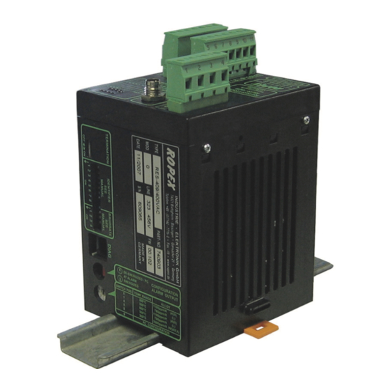
RESISTRON
RES-409
Operating
instructions
Important features
•
Microprocessor technology
•
Complete control via CAN-Bus interface
•
Automatic zero calibration (AUTOCAL)
•
Automatic optimization (AUTOTUNE)
•
Automatic frequency adjustment
•
Large current and voltage range
•
0...10VDC analog output for ACTUAL temperature
•
Alarm function with fault diagnosis
•
Heatsealing band alloy and temperature range selectable
Industrie-Elektronik GmbH
Gansäcker 21
D-74321-Bietigheim-Bissingen (Germany)
GB
Tel: +49/(0)7142/7776-0
Fax: +49/(0)7142/7776-19
E-Mail:
info@ropex.de
Internet:
www.ropex.de
Data subject to change
Advertisement
Table of Contents

Related Manuals for Ropex RESISTRON RES-409


Summary of Contents for Ropex RESISTRON RES-409
- Page 1 Large current and voltage range • 0…10VDC analog output for ACTUAL temperature • Alarm function with fault diagnosis • Heatsealing band alloy and temperature range selectable Industrie-Elektronik GmbH Tel: +49/(0)7142/7776-0 E-Mail: info@ropex.de Gansäcker 21 Fax: +49/(0)7142/7776-19 Internet: www.ropex.de D-74321-Bietigheim-Bissingen (Germany) Data subject to change...
-
Page 2: Table Of Contents
Contents Safety and warning notes ....3 Startup and operation ....15 Use . -
Page 3: Safety And Warning Notes
The resistance of the heatsealing band which is used must have a positive minimum Only the original ROPEX PEX-W2 current temperature coefficient in order to guarantee transformer may be used. Other transformers trouble-free... -
Page 4: Line Filter
Line filter DIN EN 61010-1 Safety provisions for electrical The use of an original ROPEX line filter is mandatory in (VDE 0411-1) measuring, control and laboratory order to comply with the standards and provisions devices (low voltage directive). -
Page 5: Principle Of Operation
Principle of operation The use of RESISTRON temperature controllers • Increased machine capacity results in: • Extended life of the heatsealing bands and teflon coatings • Repeatable quality of the heatseals under any conditions • Simple operation and control of the sealing process Principle of operation The resistance of the heatsealing band, which is allows optimum adaptation to the load and to the... -
Page 6: Description Of The Controller
Description of the controller Description of the controller microprocessor technology endows be used to control all the controller functions and RESISTRON temperature controller RES-409 with interrogate controller information. previously unattainable capabilities: The ACTUAL temperature of the heatsealing band is supplied to the CAN-Bus interface and to an analog •... -
Page 7: Modifications (Mods)
Designed according to VDE 0570/EN 61558 with a one-section bobbin. Optimized for impulse operation with RESISTRON temperature controllers. Specified according to the heatsealing application ROPEX Application Report). Booster B-xxx400 External switching amplifier, necessary for high primary currents (continuous current > 5A, pulsed current > 25A). -
Page 8: Technical Data
Technical data Technical data Type of construction Housing for installation in the electrical cabinet Snaps onto a standard top hat rail (DIN TS35 rail, 35mm) acc. to DIN EN 50022 Dimensions: 90 x 75mm; height: 135mm (incl. terminals) Line voltage All controllers manufactured as of January 2004: 115VAC version: 115VAC -15%…120VAC +10% (equivalent to 98…132VAC) 230VAC version: 230VAC -15%…240VAC +10% (equivalent to 196…264VAC) -
Page 9: Dimensions
Dimensions Housing material Plastic, UL-94-1, self-extinguishing Connecting cables Rigid or flexible; 0.2…2.5mm² (AWG 24…12) Type / cross-sections Plug-in connectors Dimensions 75.0 90.0 Installation See also section 1 "Safety and warning notes" on 1. Switch off the line voltage and verify that all circuits page 3. -
Page 10: Installation Steps
8.6 "Wiring diagram (standard)" on page 13 impulse transformer windings. and the ROPEX Application Report. The information 6. Make sure that the wiring conforms to the relevant provided in section 8.2 "Installation steps" on national and international installation regulations. -
Page 11: Power Supply
Use transformers with a one-section bobbin. The power, duty cycle and voltage values must be determined individually according to the application SEC. ROPEX Application Report and "Accessories" leaflet for impulse transformers). Wiring The wire cross-sections depend on the application ROPEX Application Report). -
Page 12: Line Filter
CE mark. The wiring instructions contained in section 8.3 "Power ROPEX line filters are specially optimized for use in supply" on page 11 must be observed. RESISTRON control loops. Providing they are installed... -
Page 13: Wiring Diagram (Standard)
Installation Wiring diagram (standard) CAN bus Line filter LF-xx480 Plug assignment RES-409 LINE 4 = blue (also with MOD 01) 1 = black 3 = brown CAN bus Plug 1 3-pole CAN bus Controller Bus GND electrically isolated CAN bus Plug 2 3-pole prim. -
Page 14: Wiring Diagram With Booster Connection (Mod 26)
Installation Wiring diagram with booster connection (MOD 26) CAN bus Line filter LF-xx480 Plug assignment RES-409 LINE 4 = blue (also with MOD 01) 1 = black 3 = brown Booster CAN bus Plug 1 CAN bus 3-pole Controller Bus GND electrically isolated CAN bus... -
Page 15: Startup And Operation
U and the secondary current I to the correct jumpers. position for your application. You can find the exact configuration of the DIP switches in the ROPEX Application Report calculated for your particular application. RES-409 Page 15... - Page 16 6...60V 60...200A 20...120V 120...400A If the secondary current I is less than 30A, the PEX-W2 current transformer must have two turns ROPEX Application Report). 9.2.2 Configuration of the alarm relay Alarm relay de- energized by alarm DE-ENERGIZED CONFIGURATION AT ALARM...
- Page 17 Startup and operation 9.2.3 Configuration of the CAN interface can be set. It is also possible to activate a terminating resistance. The CAN interface of the RES-409 is configured with DIP switches. The baud rate and some of the identifiers IDENTIFIER ID.
-
Page 18: Heatsealing Band
Startup and operation The least significant bit has a fixed value of 1 for has a value one higher than for received CAN sending CAN messages: The identifier for CAN messages. messages sent by the RES-409, in other words, always DIP.1 DIP.2 DIP.3 DIP.4 DIP.5 ID.10 ID.9 ID.8 ID.7 ID.6 A new DIP switch setting does not take effect... -
Page 19: Startup Procedure
47 to 63Hz. 3. The settings of the coding switches on the controller Continue with section 9.4, steps 4 to 8. depend on the ROPEX Application Report, the RES-409 Page 19... -
Page 20: Controller Functions
Yellow LED, lit during heating phase. RESISTRON µP-Controller Red LED, lights up or blinks to indicate ALARM. ROPEX INDUSTRIE - ELEKTRONIK 10.2 CAN protocol The following sections describe only controller-specific functions. For general information about the CAN bus... -
Page 21: Receiving Can Messages
Controller functions 10.3 Receiving CAN messages The complete command set of the RES-409 is shown in the table below: Address Value Meaning 0000 0…T Store set point 0 (in °C) 0001 0…T Store set point 1 (in °C) 0002 0…T Store set point 2 (in °C) 0003 0…T... - Page 22 Controller functions 10.3.2 START/STOP command The "value" parameter in the START command (address 5) has the following structure: Bit no. Name Meaning Bits 0…7 Heating time Time in 10ms resolution until the control process is automatically deactivated (at least 50ms). Bits 8…9 Set point Number of the required set point (0…3)
- Page 23 Controller functions You must always execute the AUTOCAL Actual value function after changing controller Set+ ∆ϑ version. 10.3.6 Reset Set+ ∆ϑ This command is used to reset the controller. If the controller reports alarm section 10.4.1 "Controller status" on page 24), it must be reset with Time Temperature OK this command (and possibly also with the AUTOCAL...
-
Page 24: Sending Can Messages
Controller functions 10.4 Sending CAN messages The send command set of the RES-409 is shown in the table below: Address Value Meaning 0000 0…T Current set point 0 (in °C) 0001 0…T Current set point 0 (in °C) 0002 0…T Current set point 0 (in °C) 0003 0…T... -
Page 25: Temperature Indication
Controller functions 10.4.2 Acknowledgment message command. This message contains the current actual value and the most important status information: The RES-409 automatically sends an acknowledgment message (address 9) after every START/STOP Bit no. Name Meaning 0…8 Actual value Current actual value (in °C) Sign Sign of the actual value. - Page 26 An indicating instrument can be connected to this output in order to visualize the temperature of the heatsealing band. The characteristics of the ROPEX ATR-x temperature meter (size, scaling, dynamic response) are ideally suited to this application and this instrument should therefore always be used ( section 5 "Accessories...
-
Page 27: System Monitoring/Alarm Output
Controller functions 10.6 System monitoring/alarm output Error code output via the CAN protocol If an error occurs, the alarm bit is set in the controller To increase operating safety and to avoid faulty status (bit 4) ( section 10.4.1 "Controller status" on heatsealing, controller incorporates... - Page 28 Controller functions Page 28 RES-409...
-
Page 29: Fault Areas And Causes
Controller functions 10.8 Fault areas and causes Temperature controller HARDWARE The table below explains the possible fault causes. Fault area Explanation Possible causes Load circuit interrupted after U - Wire break, heatsealing band break - Contact to heatsealing band defective pickoff point PEX-W2 current transformer measuring wires from current transformer interrupted... -
Page 30: Factory Settings
Factory settings Factory settings The RESISTRON temperature controller RES-409 is configured in the factory as follows: DIP switches = 6…60VAC = 30…100A secondary voltage and current I DIP switches:2 ON 1, 3, 4, 5 OFF Plug-in jumper Alarm relay energized by alarm alarm relay SWITCH-POS. -
Page 31: How To Order
Line filter LF- . . 480 06: Continuous current 6A, 480VAC, Art. No. 885500 35: Continuous current 35A, 480VAC, Art. No. 885506 Impulse transformer See ROPEX Application Report for design and ordering information Temp. meter ATR- . 3: 300°C range, Art. No. 882130 5: 500°C range, Art. -
Page 32: Index
Index Index Impulse transformer Installation ACTUAL temperature Installation procedure Actual value output Installation regulations Alarm output Alarm relay Alloy Ambient temperature Line filter Analog temperature meter Line frequency Application Line voltage Application Report AUTOCAL Automatic zero calibration Maintenance AUTOTUNE Modifications (MODs) MODs Booster Burning in heatsealing band...
Need help?
Do you have a question about the RESISTRON RES-409 and is the answer not in the manual?
Questions and answers