Table of Contents
Advertisement
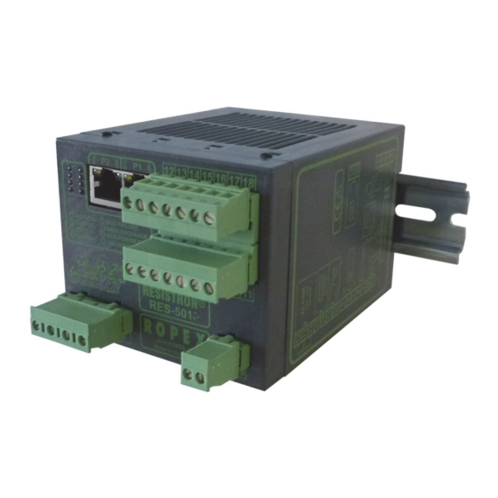
RESISTRON
RES-5011
Operating
instructions
Important features
•
Microprocessor technology
•
Complete control via PROFINET interface (2 x RJ-45)
•
Automatic zero calibration (AUTOCAL)
•
Automatic optimization (AUTOTUNE)
•
Automatic configuration of the secondary voltage and current ranges (AUTORANGE)
•
Automatic phase angle compensation (AUTOCOMP)
•
Automatic frequency adjustment
•
Large current and voltage range
•
Booster connection as standard
•
0...10VDC analog output for ACTUAL temperature
•
Alarm function with error diagnosis
•
Heatsealing band alloy and temperature range selectable
Industrie-Elektronik GmbH
Adolf-Heim-Str. 4
74321-Bietigheim-Bissingen (Germany)(Germania)(RFA)(Германия)(Alemania) Technische Änderun-
Tel.Тел: +49 7142 7776-0
FaxФакс: +49 7142 7776-211
E-MailЭл. почта:
info@ropex.de
InternetИнтернет:
www.ropex.de
Advertisement
Table of Contents

Related Manuals for Ropex RESISTRON RES-5011


Summary of Contents for Ropex RESISTRON RES-5011
- Page 1 0…10VDC analog output for ACTUAL temperature • Alarm function with error diagnosis • Heatsealing band alloy and temperature range selectable Industrie-Elektronik GmbH Tel.Тел: +49 7142 7776-0 E-MailЭл. почта: info@ropex.de Adolf-Heim-Str. 4 FaxФакс: +49 7142 7776-211 InternetИнтернет: www.ropex.de 74321-Bietigheim-Bissingen (Germany)(Germania)(RFA)(Германия)(Alemania) Technische Änderun-...
-
Page 2: Table Of Contents
Contents General information ....3 Startup and operation ....20 Copyright . -
Page 3: General Information
The temperature coefficient must be taken from the in the "Technical Data" without impairing its operational ROPEX application report and must be set accordingly. safety. Installation and maintenance may only be The use of incorrect alloys with a too low... -
Page 4: Line Filter
The use of an original ROPEX line filter is mandatory in posal of such waste in an environmen- order to comply with the directives mentioned in tally sound way. - Page 5 VDE 0551/EN 61558 or independently operable devices. They are used by the UL 5058 for safety reasons. machinery manufacturer to form a sealing system by July 12, 2020 J. Kühner (CEO) ROPEX Industrie-Elektronik GmbH Adolf-Heim-Str. 4 74321 Bietigheim-Bissingen (Germany) RES-5011 Page 5...
-
Page 6: Application
Application Application This RESISTRON temperature controller is an integral • Group packaging machines part of the "5000" series, the key feature of which is its • L-sealers microprocessor technology. RESISTRON • etc. temperature controllers are used to control the temperature of heating elements (heatsealing bands, The use of RESISTRON temperature controllers beaded bands, cutting wires, heatsealing blades, results in:... -
Page 7: Description Of The Controller
Description of the controller wiring, the timing signals, and the controller itself – are fully compatible with one another. We will be pleased to contribute our many years of experience your towards optimizing heatsealing system. Heatsealing band R = f (T) RESISTRON controller Actual value Current... -
Page 8: Accessories And Modifications
Designed according to VDE 0570/EN 61558 with a one-section bobbin. Optimized for impulse operation with RESISTRON temperature controllers. Specified according to the heatsealing application ( ROPEX Application Report). Communication interface CI-USB-1 Interface for connecting a RESISTRON temperature controller with a diagnostic interface (DIAG) to the PC (USB port). -
Page 9: Modifications (Mods)
Accessories and modifications Modifications (MODs) MOD 01 Amplifier secondary voltages Owing to its universal design, the RES-5011 = 0,2…60VAC). This modification is necessary, for RESISTRON temperature controller is suitable for a example, for very short or low-resistance heatsealing very wide range of heatsealing applications. bands. -
Page 10: Technical Data
Heatsealing band The temperature range and temperature coefficient settings can also be specified type and temperature by means of the ROPEX visualization software (section 10.11 "Diagnostic range interface / visualization software" on page 43) in addition to the rotary coding... -
Page 11: Dimensions
Dimensions Analog output 0…10VDC, I = 5mA (actual value) Equivalent to 0…300°C or 0…500°C Terminals 17+18 Accuracy: ±1% plus 50mV Fault relay = 30V (DC/AC), I = 0.2A, changeover contact, potential-free Terminals 12, 13, 14 Power dissipation Max. 20W Ambient temperature +5…+45°C Degree of protection IP20... - Page 12 Dimensions 75.0 90.0 Page 12 RES-5011...
-
Page 13: Installation
( ROPEX Application report). The minimum possible specification for this device 1. Switch off the line voltage and verify that the circuit must be entered in the ROPEX Application Report is de-energized. based on the calculated currents. If a larger 2. -
Page 14: Installation Steps
Installation Installation steps Use heatseal bands with suitable temperature coefficient Heatseal element push-on with coppered ends connectors Heatsealing band R= f (T) No additional Connect U measuring resistance wires directly to in secondary heatsealing band ends Note circuit number Sufficient wire of turns Twisted cross-section... -
Page 15: Power Supply
Connect core to ground. Use transformers with a one section bobbin. The power, duty cycle and voltage values must be deter- mined individually according to the application ( ROPEX SEC. Application Report and "Accessories" leaflet for impulse transformers). -
Page 16: Line Filter
Installation Line filter ROPEX line filters are specially optimized for use in RESISTRON control loops. Providing that they are installed and wired correctly, they guarantee compli- To comply with EMC directives – corresponding to ance with the EMC limit values. - Page 17 Installation 8.5.1 PEX-W4 terminal wires terminal block Snap-on for DIN-rail 35 x 7.5 mm or 35 x 15 mm (DIN EN 50022) 8.5.2 PEX-W5 Mounting on DIN-rail 35 x 7.5 mm or 35 x 15 mm (DIN EN 50022). RES-5011 Page 17...
-
Page 18: Wiring Diagram (Standard)
Installation Wiring diagram (standard) Line filter LF-xx480 RES-5011 LINE Ethernet PORT 1 (RJ45) Ethernet module electrically isolated prim. Shield Impulse Ethernet transformer PORT 2 (RJ45) (for assignment sec. see PORT 1) Ground Heat- Must be grounded sealing externally to band prevent twisted electrostatic... -
Page 19: Wiring Diagram With Booster Connection
Installation Wiring diagram with booster connection Line filter LF-xx480 RES-5011 LINE Ethernet PORT 1 (RJ45) Booster Ethernet twisted module Max. length 1m electrically isolated prim. Shield Impulse Ethernet transformer PORT 2 (RJ45) (for assignment sec. see PORT 1) Ground Heat- Must be grounded sealing externally to... -
Page 20: Startup And Operation
(or several voltage and current ranges times) through the PEX-W2 or PEX-W3 current trans- The secondary voltage and current ranges are former ( ROPEX Application Report). automatically configured by the automatic calibration Page 20 RES-5011... - Page 21 "Parameter object (class: 0x0F)" on page 32). switches: If the switch is set to "9", more temperature ranges and Rotary coding IP address alloys can be selected by means of the ROPEX switch visualization software ( see section 10.11 "Diagnostic interface / visualization software"...
-
Page 22: Replacing And Burning In The Heatsealing Band
URATION" position is selected, the behavior of the appears when the controller is switched on alarm output can be configured in more detail by means ( section 10.17 "Error messages" on page 45). ROPEX visualization software ( see section 10.11 "Diagnostic interface / visualization soft- ware"... -
Page 23: Startup Procedure
"AUTOCAL" LED when the voltage is switched on, section 9.2 "Controller configuration" on page 20 the configuration of this controller has been and ROPEX Application Report). Repeat the changed by means of the visualization software calibration after the controller has been configured (... - Page 24 Startup and operation 9.4.2 Restart after replacing the the EtherNet/IP protocol) has a harmonious motion, in other words it must not jump abruptly, fluctuate, or heatsealing band deviate temporarily in the wrong direction. This kind To replace the heatsealing band, proceed as described of behavior would indicate that the U measurement section 9.3...
-
Page 25: Controller Functions
Lit during heating phase. (yellow LED) ALARM Lit or blinking to indicate fault. www.ROPEX.de (Red LED) In addition to the functions shown in the diagram by the LEDs. These states are described in detail in the above, various controller operating states are indicated... - Page 26 Controller functions BLINKS slowly (1Hz) BLINKS fast (4Hz) Lit continuously AUTOCAL requested but "RS" bit is set (reset) function disabled (e.g. AUTOCAL executing AUTOCAL START active) (yellow) LED blinks with a different frequency: Supply voltages incorrect (too low) START requested but function is locked (e.g.
-
Page 27: Ethernet/Ip Communication
(support@ropex.de) (e.g. if it is switched off in order to open a downloaded from our website (www.ropex.de). door), error code 901 or 201 (error group 7, no line After the required device description file has been voltage / sync signal) appears on the controller and linked into the configuring tool, you must assign an IP the fault relay is switched. -
Page 28: Communication Protocol
Controller functions 10.4 Communication protocol information and the control functions, to enable it to be decoded more easily by the EtherNet/IP scanner. The communication protocol consists of 2x16 bit input Bits 0…7 form the low byte and bits 8…15 the words and 3x16 bit output words (from the point of view high byte ("INTEL format"). - Page 29 Controller functions 10.5.1 Automatic zero calibration Reasons for disabled AUTOCAL function: "AUTOCAL" (AC) 1. An "AUTOCAL" request cannot be processed until 10 seconds after the controller is switched on. Owing to the automatic zero calibration (AUTOCAL) During this time the controller reports "AUTOCAL function, there is no need to adjust the zero point disabled"...
-
Page 30: Output Data
Controller functions 10.5.3 Reset (RS) output. As soon as the bit is reset, new measuring impulses are generated, all error messages are This bit resets the controller if the controller reports a evaluated, and the actual value is updated again. fault. - Page 31 Controller functions 10.6.2 AUTOCAL disabled (AG) Actual value Set+ Δϑ If the "AG" bit is set, the AUTOCAL function is upper temporarily disabled. This is the case if "START" is active or if the heatsealing band is still in the cooling phase.
-
Page 32: Parameter Object (Class: 0X0F)
Controller functions 10.6.8 Actual value b.) Temperature OK Actual value All 16 bits of the first word must be interpreted as a Set+ Δϑ upper signed number (twos complement notation). During the calibration procedure or if a fault is signaled, the actual value is 0. - Page 33 Controller functions Attri- Default Instance Name Value range Data type bute ID value USINT Lower temperature OK threshold 3…99K USINT Link path length EPATH Link path 20 0F 24 02 30 01 WORD Descriptor 0x0000 USINT Data type 0xC6 USINT Data length USINT Upper temperature OK threshold...
- Page 34 Controller functions Attri- Default Instance Name Value range Data type bute ID value USINT Measuring impulse duration 1.7ms 1.7…3.0ms (17) (17…30) USINT Link path length EPATH Link path 20 0F 24 06 30 01 WORD Descriptor 0x0004 (scaling supported) USINT Data type 0xC6 USINT...
- Page 35 Controller functions Attri- Default Instance Name Value range Data type bute ID value USINT Maximum temperature 300°C 200…500°C USINT Link path length EPATH Link path 20 0F 24 0A 30 01 WORD Descriptor 0x0000 USINT Data type 0xC7 USINT Data length BOOL Temperature diagnosis Off (0)
- Page 36 Controller functions Attri- Default Instance Name Value range Data type bute ID value UINT Heatup timeout 0…999 (100ms steps) (0…99.9s) USINT Link path length EPATH Link path 20 0F 24 0D 30 01 WORD Descriptor 0x0004 (scaling supported) USINT Data type 0xC7 USINT Data length...
- Page 37 Non-volatile 300°C TCR = 3500 ppm/K, Save Instance 1 Instance 1 e.g. LEX3500 Instance 2 Instance 2 PC configuration PC configuration Restore (ROPEX (ROPEX visualization visualization software) software) Instance N Instance N Rotary coding Rotary coding switch switch setting setting...
- Page 38 U and I measuring 10.7.4 Variable calibration temperature signals for special heatsealing applications ( ROPEX Application Report). The "AUTOCOMP" function is The calibration temperature is set to 20°C as default. provided for this purpose. The following settings are You can change it to another value between 0°C and...
- Page 39 Controller functions AUTOCAL AUTOCAL <2.0s 24VDC "AC" Function Function AUTOCOMP AUTOCOMP AUTOCAL AUTOCAL "AUTOCAL" "AUTOCAL" "OUTPUT" "OUTPUT" The "OUTPUT" LED blinks repeatedly when the The "OUTPUT" LED blinks repeatedly when the "AUTOCOMP" function is executed and the actual "AUTOCOMP" function is executed and the actual value output (terminals 17+14) is set to 0…3°C (i.e.
- Page 40 This timeout starts when the "ST" bit is set. The communication and the digital temperature display RES-5011 then monitors the time required for the in the ROPEX visualization software. It has no ACTUAL temperature to reach 95% of the SET effect on the ACTUAL temperature that appears at temperature.
-
Page 41: Undervoltage Detection
Controller functions The various hold modes are shown below: No more heatsealing processes take place and no more measuring impulses are generated. Normal "ST" bit operation is resumed when the input voltage returns to the specified tolerance range again. Standby mode is indicated by 0…3 °C (i.e. approx. 0V) at the analog output. -
Page 42: 10.10 Booster Connection
Controller functions The relationship between the change in the output The characteristics of the ROPEX ATR-x temperature voltage and the ACTUAL temperature is linear. meter (size, scaling, dynamic response) are ideally suited to this application and this instrument should 0 - 300°C range °C... -
Page 43: Diagnostic Interface / Visualization
"Diagnostic interface / visualization software" on bit = 1). This counter can only be displayed and not page 43). reset. It can only be displayed using the ROPEX The clock is operated by means of a visualization software ( section 10.11 "Diagnostic maintenance-free capacitor. -
Page 44: 10.16 System Monitoring / Alarm Output
1. BLINKS fast (4Hz): value does not change any more. The AUTOCAL function should be executed (error If there is a ROPEX analog temperature meter (i.e codes 104…106, 211, 302, 303). ATR-x) connected to the analog output of the controller, 2. -
Page 45: 10.17 Error Messages
300 500 10 can be displayed via the EtherNet/IP interface and using ROPEX visualization software An error message can only be reset by ( section 10.11 "Diagnostic interface / visualization setting the "RS" bit or by momentarily software"... - Page 46 Controller functions Teil 1 von 3: Error messages (faults) NOTE: The specified error messages are initially output as faults (stable error voltage level at the actual value output; alarm LED lit continuously; alarm relay is energized). Act. value Action Action if machine Error output;...
- Page 47 Controller functions Teil 2 von 3: Error messages (warnings) NOTE: The specified error messages are initially output as warnings (actual value output jumps back and forth between two values; alarm LED blinks; alarm relay is de-energized). When the "START" signal is activated, the warning changes to a fault (actual value output no longer jumps back and forth, see bold italic values;...
-
Page 48: 10.18 Fault Areas And Causes
Controller functions Teil 3 von 3: Error messages (warnings) NOTE: The specified error messages are initially output as warnings (actual value output jumps back and forth between two values; alarm LED blinks; alarm relay is de-energized). When the "START" signal is activated, the warning changes to a fault (actual value output no longer jumps back and forth, see bold italic values;... - Page 49 Controller functions The table below explains the possible fault causes. Fault area Explanation Possible causes Load circuit interrupted after U - Wire break, heatsealing band break - Contact to heatsealing band is defective pickoff point PEX-W2/-W3 current transformer measurement cable from current transformer interrupted signal interrupted - Wire break, triac in controller defective Primary circuit interrupted...
-
Page 50: Factory Settings
Factory settings Factory settings The RES-5011 RESISTRON temperature controller is configured at the factory as follows: Rotary coding switch Heatsealing band alloy: Alloy A20 Temperature range: 300°C heatsealing band alloy Rotary coding switch: „0“ position SWITCH POS. temperature range 300°C Jumper Fault relay is energized at alarm fault relay... -
Page 51: How To Order
Line filter LF- . . 480 06: Continuous current 6A, 480VAC, Art. No. 885500 35: Continuous current 35A, 480VAC, Art. No. 885506 Impulse transformer See ROPEX Application Report for design and ordering information Communication interface CI-USB-1 Art. No. 885650 Temp. meter ATR - . -
Page 52: Index
Index Index Nummern Error messages Ethernet / IP interface 24VDC supply voltage Extended controller diagnosis External switching amplifier "AA" bit "AC" bit Factory settings Actual value Fault Actual value output Fault relay "AG" bit Fehlerbereiche "AL" bit Fuse Alarm output Alloy Ambient temperature Analog temperature meter... - Page 53 Index Temperature diagnosis Temperature meter "RA" bit Temperature OK Replacing the heatsealing band Temperature range Reset Temperature reached "RS" bit Time Time stamp "TO" bit Set point Total cycle counter Standby mode Transformer Start Transportation "START" bit Type of construction Startup System diagnosis System monitoring...
Need help?
Do you have a question about the RESISTRON RES-5011 and is the answer not in the manual?
Questions and answers