
Related Manuals for Avigilon 2.0C-H6A-BO1-IR


Summary of Contents for Avigilon 2.0C-H6A-BO1-IR
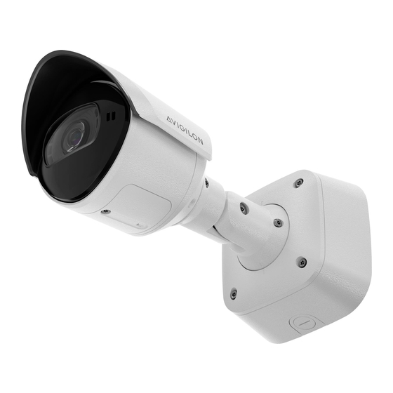
- Page 1 Installation Guide Avigilon H6A and H6X Bullet Camera Models: 2.0C-H6A-BO1-IR 6.0C-H6A-BO1-IR 4.0C-H6X-BO1-IR 4.0C-H6A-BO1-IR 8.0C-H6A-BO1-IR 8.0C-H6X-BO1-IR ...
- Page 2 © 2023, Avigilon Corporation. All rights reserved. AVIGILON, the AVIGILON logo, AVIGILON CONTROL CENTER, and ACC are trademarks of Avigilon Corporation. ONVIF is a trademark of Onvif, Inc. Covered by one or more claims of the patents listed at patentlist.hevcadvance.com. Other names or logos mentioned herein may be the trademarks of their respective owners.
- Page 3 Installation must be performed by qualified personnel only, and must conform to all local codes. Any external power supply connected to this product may only be connected to another Avigilon product of the same model series. External power connections must be properly insulated.
- Page 4 (1) this device may not cause harmful interference, and (2) this device must accept any interference received, including interference that may cause undesired operation. Avigilon Corporation hereby declares that the devices outlined in this user manual conform to FCC Part 15, subpart B, section 15.107(a), 15.107(d) and section 15.109(a).
- Page 5 For Korea IR Safety Information Use appropriate shielding or eye protection. Disposal and Recycling Information When this product has reached the end of its useful life, please dispose of it according to your local environmental laws and guidelines. European Union: This symbol means that according to local laws and regulations your product should be disposed of separately from household waste.
-
Page 6: Table Of Contents
Table of Contents Overview Junction Box View Rear View Front View Configuration Panel View Side View Installation Pre-Deployment In-Box Configuration Camera Package Contents Installation Steps Mounting and Aiming Video Analytics Cameras Installing the Junction Box Accessing Cables through the Side Conduit Connecting Cables Mounting the Camera Aiming the Camera... - Page 7 Setting the IP Address Using the ARP/Ping Method Limited Warranty and Technical Support...
-
Page 8: Overview
Overview Junction Box View 1. Camera Mounts Points for installing the camera to the mounting bracket. 2. Mounting hinge Point to hold the camera to the junction box while connecting the required cables. 3. Cable hooks Points to wrap the excess cable length around. 4. -
Page 9: Rear View
Rear View 1. Camera mounting screws Screws for mounting the camera to the junction box. 2. Power and I/O cable connectors Cable connectors for connecting the camera cables to auxiliary power and I/O devices. For more information, see Connecting to Power and External Devices on page 20. -
Page 10: Front View
Front View 1. Microphone Built-in microphone records audio when enabled. For more information, see (Optional) Enabling the Microphone on page 18. Note: Microphone is not available on H6X camera models. 2. Configuration panel cover Covers the configuration panel. For more information on the configuration panel, see the Configuration Panel View on the next page. -
Page 11: Configuration Panel View
Provides information about device operation. For more information, see Connection Status LED Indicator on page 23. 4. USB-C Accepts a USB type-C to USB adapter. Only required when using the Avigilon USB Wi-Fi Adapter. For more information, see (Optional) Using the USB Wi-Fi Adapter on page 16. Configuration Panel View... -
Page 12: Side View
Side View 1. Sun shroud A cover to help protect the lens against glare from the sun. 2. Mount arm Adjustable mount arm for positioning the camera. 3. Adjustment screws Provides a locking mechanism for the mount arm. Side View... -
Page 13: Installation
Installation Pre-Deployment In-Box Configuration The camera comes equipped with an RJ45 connector that is accessible from the outside of the box for users that want to configure camera settings before installing the camera. The RJ45 connector is accessible through the small flap on the side of the camera box for easy configuration before unpacking the camera. 1. -
Page 14: Camera Package Contents
Camera Package Contents Avigilon H6A or H6X Bullet Camera Mounting template sticker 4 screws and anchors for solid walls T20 Pin-In star-shaped driver Junction Box Wall plate Aux terminal block I/O Terminal Block ... -
Page 15: Installation Steps
The camera should be mounted to a stable surface to minimize the physical movement of the camera after installation. For more details, see Designing a Site for Video Analytics. The document is available on the Avigilon website. Installing the Junction Box When installing the junction box, the cables for the camera can be accessed through either a hole in the wall or from a side conduit entry into the junction box. - Page 16 3. Fasten the junction box to the mounting surface and pull the cords through. Note: It is recommended that silicone sealant be applied around the edge of the junction box to prevent moisture from entering the mounting surface. 4. Hook the camera onto the junction box using the mounting hooks, and let the camera hang. Installing the Junction Box...
-
Page 17: Accessing Cables Through The Side Conduit
Accessing Cables through the Side Conduit 1. Use the mounting template to drill four mounting holes into the mounting surface. 2. Secure the conduit pipe in place using a pipe clamp. 3. Pull the cables through the conduit and wrap the excess cable length around the cable hooks. 4. -
Page 18: Connecting Cables
Note: It is recommended that silicone sealant be applied around the edge of the junction box to prevent moisture from entering the mounting surface. 6. Hook the camera onto the junction box using the mounting hooks, and let the camera hang. Connecting Cables Before connecting any cables, ensure that the cable connections are properly protected from moisture and corrosion. - Page 19 5. Thread the cable through the junction box and sit the grommet in the cable hole of the junction box. 6. Connect a network cable to the Ethernet port (RJ-45 connector). The Link LED indicator will turn on once a network link has been established. 7.
-
Page 20: Mounting The Camera
Mounting the Camera Once all the cable connections have been made, secure the camera to the mounting bracket. 1. Tuck the extra lengths of cables into the cable entry hole. 2. Secure the camera to the mounting bracket: a. Raise the camera until it covers the mounting bracket. b. - Page 21 3. To use the camera in portrait mode instead of landscape mode: a. Use a T20 Pin-In star-shaped driver to unscrew and remove the sun shroud mount from the camera. Note: The sun shroud should only be removed when the camera is installed indoors and space is limited.
-
Page 22: Removing The Configuration Panel Cover
5. In the camera web browser interface or the Avigilon Control Center software adjust the camera’s Image and Display settings. You can set the zoom position, focus and change the image rotation. Removing the Configuration Panel Cover 1. Use a T20 Pin-In star-shaped driver to unscrew the configuration panel cover. -
Page 23: (Optional) Using The Usb Wi-Fi Adapter
For more information, see the Avigilon Cloud Services User Guide. Tip: If you are connecting your Avigilon camera to a 3rd party VMS, you will need to set up the first user through the camera's Web Interface, USB Wifi Adapter, or Camera Configuration Tool before you connect to the 3rd party VMS. -
Page 24: Accessing The Live Video Stream
Zooming and Focusing the Camera In the camera web browser interface or the Avigilon Control Center software, use the camera’s Image and Display settings to zoom and focus the camera. a. Use the zoom buttons to zoom the camera in or out. -
Page 25: (Optional) Enabling The Microphone
Internal Mic — configures the gain for the microphone that is built into the camera. For more information, see the Avigilon Control Center Client User Guide. (Optional) Configuring microSD Card Storage To use the camera’s onboard storage feature, you must insert 1 microSD card into a microSD card slot. While... -
Page 26: Configuring The Camera
For more information, see the Camera Configuration Tool User Guide. If the camera is connected to the Avigilon Control Center system, you can use the client software to configure the camera. For more information, see the Avigilon Control Center Client User Guide. -
Page 27: Connecting To Power And External Devices
Connecting to Power and External Devices If PoE is not available, the camera may be powered through the auxiliary power cable using 12 V DC. The power consumption information is listed in the product specifications. Important: This product is intended to be supplied by a UL Listed Power Unit marked “Class 2” or “LPS”... -
Page 28: External Power Failover
** — Switch M — Microphone S — Speaker External Power Failover If the camera has power available from both an external Aux power supply and a PoE PSE (Power Sourcing Equipment) device, the camera will draw power from Aux. In the event that the camera loses power from the preferred Aux power supply it can transition to drawing power from the PoE PSE device. - Page 29 Important: There is a downside to having seamless failover if you aren’t using this functionality and are connecting your cameras to PoE-enabled switches while running the camera on Aux power. Since the PoE connection remains active when running on Aux power, if the camera is connected to a PoE-enabled port on a switch, the switch by default will allocate some of its overall power budget to that port.
-
Page 30: Connection Status Led Indicator
Connected to the Network Video Management software or an ACC™ Server. The default connected setting can be changed to Off using the camera's web user interface. For more information see the Avigilon IP Camera Web Interface User Guide. Troubleshooting Network Connections and LED Behavior Note: For any of the below LED behaviors, ensure that the camera is getting power and is using a good network cable before trying another solution. - Page 31 LED Behavior Suggested Solution Both LEDs are blinking several times at Perform a factory reset of the camera using the physical the same time, then pause and repeat the firmware revert button. Resetting through the camera's web blinking interface will not produce the desired result. A different LED blinking pattern than Perform a factory reset of the camera using the physical those described above...
-
Page 32: Resetting To Factory Default Settings
Resetting to Factory Default Settings If the device no longer functions as expected, you can choose to reset the device to its factory default settings. Use the firmware revert button to reset the device. The firmware revert button is shown in the following diagram: For models that feature an SD card slot, resetting the camera will not affect video that has been recorded to the SD card. - Page 33 Note: The ARP/Ping Method will not work if the Disable setting static IP address through ARP/Ping method checkbox is selected in the camera's device's web browser interface. For more information, see the Avigilon IP Camera Web Interface User Guide. Complete the following steps to configure the camera to use a specific IP address: 1.
- Page 34 Limited Warranty and Technical Support Avigilon warranty terms for this product are provided at avigilon.com/warranty. Warranty service and technical support can be obtained by contacting Avigilon Technical Support: avigilon.com/contact. Limited Warranty and Technical Support...
Need help?
Do you have a question about the 2.0C-H6A-BO1-IR and is the answer not in the manual?
Questions and answers