Table of Contents
Advertisement
Available languages
Available languages
PROJECT SOURCE and logo design are
trademarks or registered trademarks of LF,
LLC. All rights reserved.
Serial Number
Questions, problems, missing parts? Before returning to your retailer, call our customer
service department at 866-389-8827, 8 a.m. - 8 p.m., EST, Monday - Sunday. You could also
contact us at partsplus@lowes.com.
AS23019
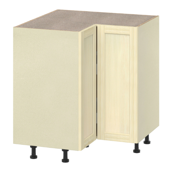
BASE CORNER CABINET
ASSEMBLY INSTRUCTION
Purchase Date
ATTACH YOUR RECEIPT HERE
1
ITEM #5217215
MODEL #SCR36
Español p. 18
Scan for assembly video
Advertisement
Chapters
Table of Contents

Related Manuals for Project Source SCR36


Summary of Contents for Project Source SCR36
- Page 1 ITEM #5217215 BASE CORNER CABINET ASSEMBLY INSTRUCTION MODEL #SCR36 PROJECT SOURCE and logo design are trademarks or registered trademarks of LF, ATTACH YOUR RECEIPT HERE LLC. All rights reserved. Español p. 18 Scan for assembly video Serial Number Purchase Date Questions, problems, missing parts? Before returning to your retailer, call our customer service department at 866-389-8827, 8 a.m.
-
Page 2: Table Of Contents
TABLE OF CONTENTS Package Contents...........................3 Hardware Contents..........................4 Safety Information..........................5 Preparation............................5 Assembly or Installation Instructions....................6 Toe-Kick Assembly Instruction......................14 Care and Maintenance..........................15 Troubleshooting..........................15 Warranty............................16 Replacement Parts..........................17... -
Page 3: Package Contents
PACKAGE CONTENTS PART DESCRIPTION QUANTITY LH & RH GABLE LH BACK RH BACK TOP & BOTTOM PANEL DOOR 1 DOOR 2... -
Page 4: Hardware Contents
HARDWARE CONTENTS (shown actual size) Minifix Cam Lock Minifix Shaft Lazy Susan PVC Adjustable Leg Qty. 22 Qty. 22 Qty. 1 Set Qty. 6 Leg Clip Hinge Mounting Plate Hinge PCC Hinge Qty. 3 Qty. 4 Qty. 2 Qty. 2 CSK Screw 5/8 Wooden Dowel Bumper 2MM... -
Page 5: Safety Information
SAFETY INFORMATION • Electric, plumbing, gas lines, and other utilities are frequently installed or embedded behind walls where cabinets are being installed. To reduce the risk of shock, explosion or injury, turn off all gas, electrical and water connections prior to performing any work. Shut off the power to any appliances and receptacles in the kitchen including lights at the fuse-breaker box. -
Page 6: Assembly Or Installation Instructions
ASSEMBLY INSTRUCTIONS 1. Using a rubber mallet, tap in wooden dowels in the correct positions as per the illustration. For added strength, apply a small amount of wood glue to each dowel prior to placement (not included). Hardware Used Wooden dowel x 22 2. - Page 7 ASSEMBLY INSTRUCTIONS 4. Place the bumper on the door as shown Hardware Used Bumper 2MM 5. Using a phillips head screwdriver, attach the mounting plate as shown in the illustration. Hardware Used Hinge mounting plate 6. Insert the pcc hinge in the bore hole. Using a phillips head screwdriver, turn the pre-installed screws clockwise to lock into place.
- Page 8 ASSEMBLY INSTRUCTIONS 7. Assemble the cabinets parts as per the illustration. Ensure all cams are locked into place before moving the cabinet. 8. Assemble the cabinets parts as per the illustration. Using a phillips head screwdriver, rotate the minifix cam clockwise to fasten into place. Ensure all cams are locked into place before moving the cabinet.
- Page 9 ASSEMBLY INSTRUCTIONS 10. Assemble the cabinets parts as per the illustration. Using a phillips head screwdriver, rotate the minifix cam clockwise to fasten into place. Ensure all cams are locked into place before moving the cabinet. 11. Position the mounting bracket for the legs on the underside of the cabinet box and using a phillips head screwdriver, secure into place with csk screws 5/8”...
- Page 12 ASSEMBLY INSTRUCTIONS 27. Mount the door on the cabinet by connecting the hinges on the door to the mounting plates on the box. Use the Hinge guide below for detailed instructions. If the adjustments to the door are needed, instructions are available on page 13 of this manual. Hinge guide Hinge PCC Hinge...
- Page 13 ASSEMBLY INSTRUCTIONS 28. YOU’RE FINISHED – ENJOY Hinge Adjustment: Side adjustment: Depth adjustment: Height adjustment: Using a phillips screwdriver, rotate Using a phillips screwdriver, rotate screw Using a phillips screwdriver, rotate screw (1) clockwise to move the door (2) clockwise to move the door forward screw (3) clockwise to move the door Door Assembly left and counter-clockwise to move the...
-
Page 14: Toe-Kick Assembly Instruction
TOE-KICK ASSEMBLY INSTRUCTION STEP- 1 • Measure the back of your toe kicks as per the above diagram. Once you have determined the location of the leg clips, mark the screw hole position with a pencil. • Using a punch or drill bit, make a pilot hole in the screw hole position. -
Page 15: Care And Maintenance
MAINTENANCE • To maintain the beauty of your finish, try to avoid direct sunlight on the cabinetry for extended periods Of time. Use a window treatment to block direct sunlight if necessary. • Avoid exposing the cabinet to extreme temperatures. CARE AND CLEANING •... -
Page 16: Warranty
What project source will do under the warranty During the warranty period, project source at its discretion, will repair or replace any part or product that proves to have substantial defects in materials or workmanship, or project source will provide an equivalent replacement product. Project source reserves the right to change specifications in design and materials without notice and with no obligation to replace products that were previously manufactured. -
Page 17: Replacement Parts
866-389-8827. All warranty claims must include the model number of the product, a copy of the original receipt, and the nature of the problem. In addition, project source may at its discretion require inspection of the installation site, photography, or authorize the prepaid return of the claimed defective part. - Page 18 ARTÍCULO #5217215 INSTRUCCIONES DE ENSAMBLAJE DEL GABINETE BASE PARA ESQUINA PROJECT SOURCE y el diseño del MODELO #SCR36 logotipo son marcas comerciales o marcas registradas de LF, LLC. Todos los derechos reservados. ADJUNTE SU RECIBO AQUÍ Vea un video del ensamblaje Número de serie...
- Page 19 ÍNDICE Contenido del paquete........................20 Aditamentos.............................21 Información de seguridad.........................22 Preparación............................22 Instrucciones de ensamblaje o instalación..................23 Instrucciones de ensamblaje del rodapié..................31 Cuidado y mantenimiento........................32 Solución de problemas........................32 Garantía............................33 Piezas de repuesto..........................34...
-
Page 20: Contenido Del Paquete
CONTENIDO DEL PAQUETE DESCRIPCIÓN PIEZA DESCRIPCIÓN CANTIDAD GABLETE IZQUIERDO Y DERECHO PARTE POSTERIOR IZQUIERDA PARTE POSTERIOR DERECHA PANEL SUPERIOR E INFERIOR PUERTA 1 PUERTA 2... -
Page 21: Aditamentos
ADITAMENTOS (se muestran en tamaño real) Cerrojo de leva minifija Eje minifijo Bandeja giratoria Pata ajustable de PVC Cant. 22 Cant. 22 Cant. 1 juego Cant. 6 Sujetador de Placa de montaje Bisagra de 155° Bisagra PCC la pata de bisagras Cant. -
Page 22: Información De Seguridad
INFORMACIÓN DE SEGURIDAD Es frecuente que existan líneas eléctricas, de agua, gas u otros servicios instaladas o incrustadas detrás de las paredes donde se están instalando los gabinetes. Para reducir el riesgo de descargas eléctricas, explosiones o lesiones, desconecte las conexiones de gas, electricidad y agua antes de comenzar la instalación. -
Page 23: Instrucciones De Ensamblaje O Instalación
INSTRUCCIONES DE ENSAMBLAJE 1. Con un mazo de goma, golpee las espigas de madera en las posiciones correctas según la ilustración. Para mayor resistencia, aplique una pequeña cantidad de pegamento para madera a cada espiga antes de su colocación (no incluido). Aditamentos utilizados Espiga de madera x 22... - Page 24 INSTRUCCIONES DE ENSAMBLAJE 4. Coloque el tope en la puerta como se muestra. Aditamentos utilizados Tope de 2 mm 5. Con un destornillador Phillips, fije la placa de montaje como se muestra en la ilustración. Aditamentos utilizados Placa de montaje de bisagras 6.
- Page 25 INSTRUCCIONES DE ENSAMBLAJE 7. Ensamble las piezas de los gabinetes como se muestra en la ilustración. Asegúrese de que todas las levas estén trabadas en su lugar antes de mover el gabinete 8. Ensamble las piezas de los gabinetes como se muestra en la ilustración.
- Page 26 INSTRUCCIONES DE ENSAMBLAJE 10. Ensamble las piezas de los gabinetes como se muestra en la ilustración. Con un destornillador Phillips, gire la leva minifija en dirección de las manecillas del reloj para fijarla en su lugar. Asegúrese de que todas las levas estén trabadas en su lugar antes de mover el gabinete.
- Page 27 Fijación superior TORNILLO DE CABEZA ALOMADA TORNILLO DE CABEZA ALOMADA Fijación inferior...
- Page 29 INSTRUCCIONES DE ENSAMBLAJE 27. Instale la puerta en el gabinete conectando las bisagras de la puerta a las placas de montaje en la caja. Use la guía de bisagras a continuación para obtener instrucciones detalladas. Si es necesario hacer ajustes en la puerta, encontrará...
- Page 30 INSTRUCCIONES DE ENSAMBLAJE 28. HA TERMINADO, DISFRUTE. Ajuste de la bisagra Ajuste lateral: Ajuste de profundidad: Ajuste de altura: Con un destornillador Phillips, gire el Con un destornillador Phillips, gire el Con un destornillador Phillips, gire el tornillo (1) en dirección de las tornillo (2) en dirección de las manecillas tornillo (3) en dirección de las Ensamblaje...
-
Page 31: Instrucciones De Ensamblaje Del Rodapié
INSTRUCCIONES DE ENSAMBLAJE DEL RODAPIÉ PASO 1 Ancho del gabinete Ancho del gabinete Ancho del gabinete Ancho del gabinete • Mida la parte posterior de los No incluido, se vende por separado rodapiés como se muestra en el diagrama anterior. Una vez que haya determinado la ubicación de los sujetadores de las patas, marque la posición del orificio... -
Page 32: Cuidado Y Mantenimiento
MANTENIMIENTO • Para mantener la belleza del acabado, trate de evitar la luz solar directa sobre los gabinetes durante largos tiempos. Use una decoración de ventanas para bloquear la luz solar directa si es necesario. • Evite exponer el gabinete a temperaturas extremas. CUIDADO Y LIMPIEZA •... -
Page 33: Garantía
Project Source brindará un producto de reemplazo equivalente. Project Source, se reserva el derecho de cambiar las especificaciones en el diseño y en los materiales sin previo aviso y sin obligación de reemplazar productos fabricados previamente. -
Page 34: Piezas De Repuesto
Si después de la inspección, usted descubre que el producto está dañado o que le falta una pieza, no es necesario devolver la unidad a la tienda donde se hizo la compra. Póngase en contacto con Project Source.
Need help?
Do you have a question about the SCR36 and is the answer not in the manual?
Questions and answers