Table of Contents
Advertisement
Quick Links
Instructions
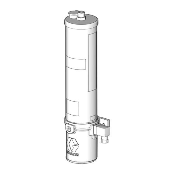
28:1 Lube Pro
Vertical Oil Pump
For pumping non-corrosive and non-abrasive lubricants only. For professional use only.
Not approved for use in European explosive atmosphere locations.
Models:
See page 2 for model information, including maximum working
pressure and approvals.
3500psi (24 MPa, 241 bar) Maximum Working Pressure
Important Safety Instructions
Read all warnings and instructions in this manual.
Save these instructions.
™
3A4033J
EN
Advertisement
Table of Contents

Related Manuals for Graco Lube Pro 24Z020


Summary of Contents for Graco Lube Pro 24Z020
- Page 1 Instructions ™ 28:1 Lube Pro Vertical Oil Pump 3A4033J For pumping non-corrosive and non-abrasive lubricants only. For professional use only. Not approved for use in European explosive atmosphere locations. Models: See page 2 for model information, including maximum working pressure and approvals. 3500psi (24 MPa, 241 bar) Maximum Working Pressure Important Safety Instructions Read all warnings and instructions in this manual.
-
Page 2: Table Of Contents
California Proposition 65 ....31 Graco Standard Warranty ....32... -
Page 3: Models
Models Models Normally Normally Part No. Size Low Level Open Closed 24Z020 0.6 L 24Z021 0.6 L 24Z022 0.6 L 24Z023 0.6 L 24Z024 0.6 L 24Z025 0.6 L 24Z026 24Z027 24Z028 24Z029 24Z030 24Z050 3A4033J... -
Page 4: Warnings
Warnings Warnings The following warnings are for the setup, use, grounding, maintenance, and repair of this equipment. The exclama- tion point symbol alerts you to a general warning and the hazard symbols refer to procedure-specific risks. When these symbols appear in the body of this manual or on warning labels, refer back to these Warnings. Product-spe- cific hazard symbols and warnings not covered in this section may appear throughout the body of this manual where applicable. - Page 5 Warnings WARNING ELECTRIC SHOCK HAZARD This equipment must be grounded. Improper grounding, setup, or usage of the system can cause electric shock. • Turn off and disconnect power at main switch before disconnecting any cables and before servicing or installing equipment. •...
-
Page 6: Typical Installation
Typical Installation Typical Installation . 1: Typical Installation Key: Main Air Supply Line Filter/Regulator/Lubricator Assembly B1 - Air Filter B2 - Air Regulator B3 - Air Lubricator Air solenoid valve (3-way) Pump module Pump outlet Bleed-type master air valve (required) High pressure lubricant supply lines (user supplied) Injector Lubricator controller... -
Page 7: Installation
Installation Installation Mount the Pump Mount the pump securely so that it cannot move around during operation. Failure to do so could result Grounding in injury or equipment damage. Install the pump in a location that will adequately sup- port the weight of the pump when it is filled with lubri- cant and also provides easy operator access to the pump air controls. -
Page 8: Air And Fluid Line Accessories
Installation Air and Fluid Line Accessories To use the air regulator reading to determine the fluid output pressure, multiply the ratio of the pump (28:1) Refer to F . 1, page 6, for the following instruction. by the air pressure shown on the regulator gauge or see Table 1: Lubricant Output and Pressure - US Install the air line accessories in the order shown in F PSI or Table 2: Lubricant Output and Pressure -... -
Page 9: Prime
Installation Prime 2. Slowly add oil (ol) until the reservoir is filled to capacity (F . 5). NOTE: NOTE: Do not fill the reservoir too quickly and overflow • Prime the pump before connecting the outlet to the reservoir capacity. supply line (G). -
Page 10: Air Lock Procedure
Installation Air Lock Procedure Refer to F . 1, page 6, for the following instruction. An air lock occurs when a bubble or pocket of air pre- vents the normal flow of the lubricant. NOTICE Running the pump dry will cause an air lock. To pre- vent an air lock, do not run the pump without lubricant. -
Page 11: Operation
Operation Operation Pressure Relief Procedure Pump Start Up Follow the Pressure Relief Procedure whenever you see this symbol. 1. Verify reservoir is filled with lubricant and system has been primed (see Prime, page 9). 2. Turn on the lubrication controller (J) power switch. This equipment stays pressurized until pressure is manually relieved. -
Page 12: Low Level Switch
Operation Low Level Switch Shut Down When the oil reservoir is full, the low level float (llf) sits in the high, raised position as shown in F . 9. Refer to F . 1, page 6, for the following instruction. To shut down the system: a. -
Page 13: Guidelines
Operation Lubrication System Sizing and Calculation Guidelines Table 1: Lubricant Output and Pressure - US NOTE: The lubricant output per pump stroke must be less than the amount of lubricant discharged per pump stroke. Injector Max Pump Minimum Maximum Pressure Recommended Pressure Volume to Lubricant... -
Page 14: Repair
Repair Repair 6. Collect the drained oil in a pail or waste container. Dispose of oil according to all regulations for proper disposal. 7. Replace drain plug (40). 8. Remove the mounting bolts (F . 12) and remove the pump from service. Seal Replacement NOTE: For most seal replacement procedures, the pump should be completely removed from service and... - Page 15 Repair Reservoir Gaskets (10) 12. Remove reservoir (11) from the air motor cylinder (3) (F . 15). If replacing the reservoir gaskets (10), 10. Use a wrench to loosen and remove the nut (17) remove gaskets from the reservoir. Dispose of the from the reservoir cover (18) (F .
- Page 16 Repair Outlet Tube O-Ring (13) and Pump Cylinder O-Ring (9). 13. Securely hold the nut (3a), located on the bottom of the pump cylinder (12), in place with a wrench. Secure a second wrench on the flats of the outlet tube (14).
- Page 17 Repair Pump Piston Subassembly (33). 20. Secure a wrench on the cover nut (1a). Turn it counter-clockwise loosen and remove the cover (1) from bottom or air motor cylinder. (F . 20). 16. Secure a wrench on the flats of piston rod (34). Use a second wrench to remove the lock nut (31) and star washer (32) from top of the piston (F .
- Page 18 Repair 21. Remove the cover (1), the cover o-ring (2) and the spring (6). Dispose of the o-ring according to all regulations for proper disposal (F . 22). . 22 . 24 25. Dispose of the piston seal (4), the o-ring (34a) and Piston Rod O-Ring (36) and Piston Seal (4) the nut (37) according to all regulations for proper 22.
-
Page 19: Reassembly
Repair Reassembly 27. Use a pick to remove the bushing (35) and u-cup seal (36) (F . 26). Use all of the new parts included in the repair / service kit even if the old parts do not appear to be worn or damaged and dispose of the old parts according to all regulations for proper disposal. - Page 20 Repair Piston Rod-O-Ring (34a) and Piston Seal (4) 7. Install the nut (37) over the end of the piston rod (34). Use two wrenches, working in opposite direc- NOTE: Do not clamp the piston rod (34) in vise. tions to tighten the nut. Secure one open end wrench to flats of piston rod and use the second 4.
- Page 21 Repair 9. Install the spring (6) over the piston rod (34) and 12. Reposition the air motor cylinder in vise to access install spring and piston rod into the air cylinder (3) the top of the air motor cylinder as shown in F .
- Page 22 Repair Outlet Tube O-ring (13) and Pump Cylinder 18. Install the outlet tube (14) on the pump cylinder (12). O-ring (9) Securely hold the nut (3a) [located on the bottom of the pump cylinder (12)] in place with a wrench. 16.
- Page 23 Repair Reservoir Gaskets (10) 21. Install the cover (18) on the reservoir (11). Torque nut (17) to 45 - 55 in. lbs. (5.1 to 6.2 N.m) (F . 41). 19. Install the reservoir gaskets (10) to the top and the bottom of the reservoir (11) as shown in F .
-
Page 24: Recycling And Disposal
Recycling and Disposal Recycling and Disposal End of Product Life At the end of the product’s useful life, dismantle and recycle it in a responsible manner. • Perform the Pressure Relief Procedure, page 11. • Drain and dispose of fluids according to applicable regulations. -
Page 25: Troubleshooting
Troubleshooting Troubleshooting Follow Pressure Relief Procedure, page 11, before checking or repairing the pump. Check all possible problems and causes before disas- sembling the pump. Problem Cause Solution 1. Adjust the air pressure/supply. No air 2. Open the bleed-type master air valve (F) (page 6). -
Page 26: Parts
Parts Parts Torque to 28 to 32 ft. lbs (37.9 to 43.4 N.m) Torque to 45 to 55 in. lbs (5.1 to 6.2 N.m) Torque to 25 to 30 in. lbs (2.8 to 3.4 N.m) Torque to 155 to 165 in. lbs (17.5 to 18.6 N.m) Torque to 12 to 15 ft. - Page 27 Parts Parts Part No Description Part No Description 15K550 MAGNET.6.35 mm diameter; 17J825 COVER, air motor ❊ ✖ 6.35 mm tall, models 24Z021, 17J826 SEAL, o-ring 24Z022, 24Z024, 24Z025, ★ 24Z027, 24Z028, 24Z030, 17J828 CYLINDER, air motor, low level, 24Z050 models 24Z021, 24Z022, 24Z024, 24Z025, 24Z027, 17K551...
-
Page 28: Dimensions And Mounting Layout
Dimensions and Mounting Layout Dimensions and Mounting Layout See Dimensions Tables, page 29 3A4033J... -
Page 29: Dimensions: Us - Inches
Dimensions and Mounting Layout Dimensions: US - inches (See Dimensions and Layout drawing, page 28) Models 24Z020, 24Z023 5.25 + 0.11 12.53 + 0.11 24Z021, 24Z022, 24Z024, 24Z025 6.8 + 0.11 5.1 + 0.11 24Z026, 24Z029 5.25 + 0.11 19.83 + 0.11 24Z027. -
Page 30: Technical Specifications
Technical Specifications Technical Specifications LubePro Vertical Oil Pump Metric Maximum fluid working pressure 3500 psi 24 MPa, 241 bar Fluid Minimum 40cSt Pressure ratio 28:1 Pump output 0.56 cu. inch/stroke Reservoir capacity 0.6 L (30 cu ni.) or 2 L (120 cu. in.) Maximum air inlet pressure 125 psi 0.86 MPa, 8.62 bar... -
Page 31: California Proposition 65
California Proposition 65 California Proposition 65 WARNING: This product can expose you to chemicals known to the State of California to cause cancer and birth defects or other reproductive harm. For more information, go to www.P65warnings.ca.gov. 3A4033J... -
Page 32: Graco Standard Warranty
With the exception of any special, extended, or limited warranty published by Graco, Graco will, for a period of twelve months from the date of sale, repair or replace any part of the equipment determined by Graco to be defective.
Need help?
Do you have a question about the Lube Pro 24Z020 and is the answer not in the manual?
Questions and answers