Advertisement
Quick Links
Advertisement

Related Manuals for Fab Fours X595X


Summary of Contents for Fab Fours X595X
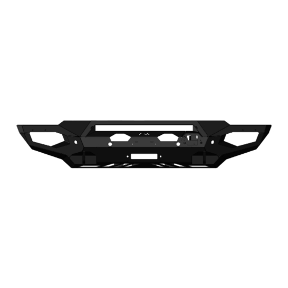
- Page 1 Installation manual matrix Front Bumper Product number: X595X Application: 2023 FORD SUPER DUTY...
- Page 2 Use own good judgment and take your time. WARNINGS • Failure to observe the following warnings • Fab Fours, Inc. only approves installing this and instructions provided in this manual product according to these written instructions could lead to severe injury and/or death.
- Page 3 SAFETY / DISCLAIMER TABLE OF CONTENTS A MESSAGE FROM THE OWNER GETTING STARTED PROVIDED MATERIAL INSTALLATION CONTACT...
- Page 4 A message from the owner Fab Fours’ was born out of a passion for customizing vehicles and a love of the outdoors. Our engineering team uses the latest 3D design software to turn new product ideas into reality. In our factory, designs come to life with the combination of cutting edge technology for metal cutting and forming and an American workforce that puts its’...
- Page 5 Getting started Before you begin the installation process of your new Fab Fours product, we suggest laying out all materials and parts on a pad or protective surface. Failure to fully account for all components before beginning installation may leave vehicle...
- Page 6 Provided materials TOOLS REQUIRED • PANEL PRY TOOL • TAPE MEASURE • SILVER MARKER • ANGLE GRINDER OR HAND FILE • DRILL • 1/4” DRILL BIT • 1/2” DRILL BIT • E6 TORX SOCKET • 1/8” ALLEN WRENCH • 8MM SOCKET WRENCH •...
- Page 7 Hardware kit | 50409-HW IDENTIFICATION Component NUMBER Description 50409-HW 1/4"-20 X 1", HEX HEAD CAP SCREW, YELLOW-ZINC, GRADE 8 50409-HW 1/4"-20, HEX NUT, YELLOW-ZINC, GRADE 8 50409-HW 1/4"-SAE, FLAT WASHER, YELLOW-ZINC, GRADE 8 50409-HW 1/4"-SAE, LOCK WASHER, YELLOW-ZINC, GRADE 8 50409-HW 1/2"-13 X 2.0", HEX HEAD CAP SCREW, YELLOW-ZINC, GRADE 8...
- Page 8 INSTALLATION Remove the plastic tow hook covers by pulling on them to release the clips. Figure 1 Figure 1 Disconnect the bumper electrical harness connected to the inside of the driver side frame rail. Figure 2 Figure 2...
- Page 9 If applicable, remove the adaptive cruise control (ACC) sensor from its mounting bracket. Figure 3 Figure 3 If applicable, disconnect the electrical connector from the ACC sensor. Figure 4 Figure 4...
- Page 10 Using an E6 torx socket remove the three (3) studs that attach the ACC bracket to the vehicle. Figure 5 Figure 5 Using an 18mm socket wrench, remove the eight (8) bolts that attach the bumper to the tow hook brackets.
- Page 11 Using a 15mm socket wrench, remove the two (2) bolts per side that attach the bumper reinforcement brackets to the frame. Figure 7 Figure 7 Using a body panel pry tool, remove the two (2) push pins attaching the shroud to the grille. The bumper can now be removed from the vehicle.
- Page 12 Using an 18mm socket wrench, remove the eight (8) bolts attaching the tow hooks to the frame and remove the tow hooks. Figure 9 Figure 9 Using an 18mm socket wrench, remove the eight (8) nuts attaching the underrun guards to the bottom of each frame rail.
- Page 13 Using an 8mm socket wrench, remove the four (4) screws in each fog light bracket to remove them from the bumper. Figure 11 Figure 11 Using a panel pry tool, remove the push pin clip. Figure 12 Figure 12...
- Page 14 Using a marker, trace the outline and the two (2) holes of the provided ACC cover plate (Part#: 23042) onto the smooth side of the provided plastic ACC filler panel (Part#: 61784). Then use a knife to cut the ACC filler panel along the marked line and use a 1/4”...
- Page 15 Remove the ACC filler panel, and use a 1/2” drill bit, drill out the previously marked spot on the ACC filler panel. Figure 16 Figure 16 Using a tape measure and marker, measure in from the corner of the ACC mounting bracket 1/4” and make a chamfer mark.
- Page 16 Using an angle grinder or hand file, remove the material previously marked on the ACC bracket. Figure 20 Figure 20 Dislodge the three (3) ACC bracket studs from the bracket towards the end with the lock nut so that the ball is visible. Figure 21 Figure 21...
- Page 17 Install the ACC bracket into the bumper. Figure 22 Figure 22 Thread the ACC bracket mounting studs into the mounting bracket in the bumper using an E6 torx socket wrench. Tighten the top stud until the sensor face is parallel to the bumper face. Figure 23A **Note: The ACC sensor can be adjusted for calibration after the bumper is installed by simply...
- Page 18 Install the two (2) provided barrel nuts onto the ACC filler panel and insert it inside the bumper. Using the two (2) provided 10-24 socket head cap screws with an 1/8” Allen wrench, install the ACC cover plate. Figure 23B Figure 23B Using a pry tool, reset the sockets in the ACC mounting bracket onto the mounting stud balls.
- Page 19 If installing lighting in the bumper do so now. Use the two (2) provided L-brackets (part#: 21871) and four (4) 1/4” hex cap screws, flat washers, lock washers, and nuts to mount the 30” lightbar. Figure 25-27 Figure 25 Figure 27 Figure 26...
- Page 20 Reinstall the front parking sensor housing, sensors, and harness into the Fab Fours bumper in the same position and orientation as they were removed from the OEM bumper. Use the provided epoxy to secure the sensor housing to the bumper shell. Zip-tie the harness to the bottom of the tabs welded to the inside of the shell under the winch access holes.
- Page 21 If installing a winch, do so now along with its fairlead per the winch manufactures instructions and with the hardware provided with the winch. Using a 3/4” socket wrench and combination wrench, install the provided bumper mounting brackets (Part#: DS-23039 / PS-23040) onto their respective frame rail end with the provided 1/2” hex head cap screws, flat washers, lock washers, and hex nuts into the top four (4) holes.
- Page 22 Using the built in hang tabs on the bumper mounting brackets, hang the bumper shell (Part#: 23038) in place in preparation for bolting. Figure 35 Figure 35 Install the four (4) provided bolt strips (Part#: 20296) inside the bumper mounts through the mounting brackets.
- Page 23 Using a 3/4” deep socket, press the four (4) provided 1/2” bolt retainer clips onto the previously installed bolt strips (one per bolt strip) to hold them in place for bumper installation. Figure 37 Figure 37 Using a 3/4” socket wrench, install the four (4) provided washer plates (Part#: 23046), 1/2” flat washers, lock washers, and hex nuts onto the previously installed bolt strips.
- Page 24 Reconnect the bumper wiring harness. Figure 39 Figure 39 INSTALLATION COMPLETE...
- Page 25 Contact information Fab Fours Inc. 2213 Industrial Park Road Lancaster, SC 29720 Phone: (866) 385-1905 Fax: 970-385-1914 Email: support@fabfours.com fabfours.com...
- Page 26 “If you’re looking for more of the same, Then you’ve come to the wrong place.” - Greg Higgs...
Need help?
Do you have a question about the X595X and is the answer not in the manual?
Questions and answers