Table of Contents
Advertisement
Quick Links
Advertisement
Table of Contents

Related Manuals for Pfeiffer Vacuum MiniTest 300


Summary of Contents for Pfeiffer Vacuum MiniTest 300
- Page 1 MiniTest 300 Operating Instructions...
- Page 2 Abb. 1 Rating plate Validity This document is valid for products with the article number MiniTest 300 PT L03 000 You can find the article number on the rating plate. This document is based on the MiniTest firmware version 1.2 and higher. To use all functions, a remote control RC500 with firmware version 1.1 or higher is needed.
-
Page 3: Table Of Contents
Connecting flange 4.2.3 Connection of optional vacuum pump 4.2.4 Electrical connections Components and accessories 4.3.1 Power supply pack for the MiniTest 300 4.3.2 Mains adapter/charger for the wireless remote control RC 500 WL 4.3.3 Sinter filter for vacuum connection 4.3.4 Calibrated test leak (pin leak) 4.3.5... - Page 4 4.5.2 User interface Technical data Mechanical data Ambient conditions Electrical data Physical data Installation Preparation Connecting the vacuum system Connecting the controller 6.3.1 Wireless remote control 6.3.2 Wired remote control Installing accessories 6.4.1 Connecting the test leak Connecting the electrical power supply Connecting external pressure gauges Operation Switching on the unit...
- Page 5 7.9.3 Calibrating the unit 7.10 Measuring 7.10.1 Preparing the measurement 7.10.2 Scale display area 7.10.3 Use helium underground 7.10.4 Leak test 7.10.5 Recording measured data 7.10.6 Evaluation of measured signals 7.10.7 Contamination 7.11 Switching Off 7.12 Disconnecting the unit Malfunctions Warning and malfunction messages Maintenance and service Taking out of service...
-
Page 6: Operating Instructions
Operating instructions Description of the target group This operating manual is intended for the user of the MiniTest 300 and for technically qualified specialists who are trained in the operation of the MiniTest 300 and have gained experience in vacuum technology, leak detection and leak testing. -
Page 7: Information, Instructions And Notes
1.3.2 Information, instructions and notes Check a precaution. ► An action to be taken Execute actions in the specified sequence. … … Shows the result of an action. • List • ... • ... Tip: Tips and useful information “Settings”: Terms in quotation marks appear on the display as text or as a button. -
Page 8: Safety
It is intended for use in vacuum leak detection. The specimen must be evacuated and its outside sprayed with helium. Tip: In order to have a comparison for the behavior of the MiniTest 300, use a reference pressure for the first measurement and observe the behavior of the MiniTest 300. -
Page 9: Dangers
Supposed risk If safe operation is no longer possible, take the unit out of service and secure it against accidentally being switched on. This can be the case, if: • the unit shows signs of damage (outside or inside), • a fluid has penetrated the unit, •... -
Page 10: Danger Due To Radio Interference
2.3.3 Danger due to radio interference CAUTION Possible danger due to radio interference! During operation of the wireless RC 500 WL, a minimum distance of 7 cm must be maintained between the remote control and personnel, with the exception of hands and wrists ►... -
Page 11: Dangers Due To Handling Of The Battery
2.3.5 Dangers due to handling of the battery Battery of the wireless remote control RC 500 WL When handling the battery of the wireless RC 500 WL, comply with the information in the operating manual for the remote control. (Document number IG0140BDE). -
Page 12: Transport, Storage, Unpacking
Transport, storage, unpacking Transport ► Transport the unit only in the original packaging. Storage NOTICE Possible material damage due to helium. Even when the unit is switched off, the sensor is affected by nearby helium. Contact with increased concentrations of helium has a negative effect on the minimum detection limit and can cause damage. -
Page 13: Description
On the rear side there is a DN KF 25 connection flange (see Fig. 3). It is used to connect the unit to the system to be tested for leaks. The MiniTest 300 has no wear parts and is therefore maintenance-free. -
Page 14: Display And Operation
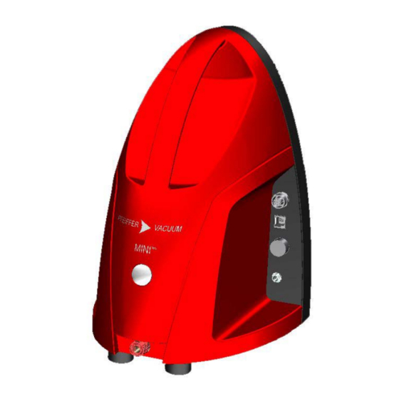
4.2.1 Display and operation On the front side there is an operating mode display, which can light up in different colors: Color Meaning Green Ready for operation or in operation Yellow No connection to the remote control RC 500/RC 500 WL and no continuous connection to the computer. -
Page 15: Connection Of Optional Vacuum Pump
Fig. 3 Vacuum connection flange of the unit 4.2.3 Connection of optional vacuum pump Fig. 4 Connection of vacuum pump... -
Page 16: Electrical Connections
All vacuum pumps that generate a final pressure that is lower than the pressure in the system can be connected. See also Chapter 4.3.5. 4.2.4 Electrical connections Fig. 5 Electrical connections on the MiniTest 300 No. Description of connection Radio transmitter: Radio transmitter for wireless remote control D-SUB (DE9) -
Page 17: Components And Accessories
Components and accessories 4.3.1 Power supply pack for the MiniTest 300 The power supply pack for the MiniTest 300 provides the supply voltage for operating the unit. On the input side the power supply pack is connected to the mains voltage by means of a mains cable. -
Page 18: Mains Adapter/Charger For The Wireless Remote Control Rc 500 Wl
4.3.2 Mains adapter/charger for the wireless remote control RC 500 WL The mains adapter/charger is used to charge the battery of the wireless remote control RC 500 WL. The coaxial power connector on the cable of the power supply pack must be connected to the remote control for charging. -
Page 19: Calibrated Test Leak (Pin Leak)
An optional calibrated test leak is installed on the system to be tested by means of a KF16 flange. It provides defined leakage. It is used to calibrate the MiniTest 300 on the system. (See also Chapter 4.4.) Fig. 8 Calibrated test leak with connection flange 4.3.5... -
Page 20: Function
Function MiniT est 300 Fig. 10 For example: Vacuum diagram of the MiniTest 300 on a system No. Description Vacuum connection flange DN KF 25 Sensor Connection of optional vacuum pump Valve Inlet with throttle valve for purging the sensor with air... - Page 21 The sensor is purged for a short time with air from outside. The air flows through the MiniTest 300 into the system being tested. (For the gas flow of the throttle valve see Chapter 5.4.)
-
Page 22: Remote Control
Remote control The remote control is used to control the unit, as well as for display and data storage. The remote control is available in two versions: • Wireless connection to the unit (RC 500 WL) (The radio transmitter is connected to the unit. Alternatively, this remote control can also be connected by cable to the unit.) •... -
Page 23: Paging Function
Locate the remote control RC 500 WL by means of an audible signal:. The remote control can be located by means of an audible signal by pressing the “Paging” button on the MiniTest 300 and there is a connection between the two devices. -
Page 24: User Interface
Switches display between measuring and search mode Adjust loudness 10 Select main menu • If the connection to the MiniTest 300 is interrupted: The graph, the numerical values of the leakage rate and of the pressure become gray. The icon for the connection status changes. - Page 25 Fig. 14 Display in case of interrupted connection 4.5.2.2 User prompts For certain operating steps the graphical interface displays text messages that prompt an action or a confirmation. Fig. 15 User prompts and confirmation during calibration The “TL” button can be used to enter the leakage rate of the test leak.
- Page 26 4.5.2.3 Menu tree The parameters of the unit are arranged in a tree structure. The top level is the main menu. From here, it branches off into the other menu levels, where all parameters can be found. (The entire menu tree is shown in Chapter 7.2.) Softkeys are used for navigating in the menu tree.
- Page 27 Fig. 18 Value to be changed with arrow keys and value entered numerically 4.5.2.5 Status of remote control and unit Fig. 19 Remote control radio scan and initialization with data transfer Fig. 20 MiniTest 300: Run-up and wait for vacuum...
- Page 28 4.5.2.6 Information The graphical interface provides various system information. Fig. 21 Information on the version and basic data 4.5.2.7 Error Messages Fig. 22 Warning 520 or calibration failed The “C” key deletes the error message if this is possible. (See also Chapter 8.1)
- Page 29 4.5.2.8 Help texts Help texts can be opened in various menus by pressing the “?” key. Fig. 23 Help texts...
-
Page 30: Technical Data
Technical data Mechanical data Fig. 24 Bottom side... - Page 31 Fig. 25 Side view Leak detector Dimensions (height x width x depth, including flange) 307 x 205 x 265 mm Free space at the top and bottom for ventilation 10 cm each Noise level <70 dB/A (acc. to IEC standard) Weight 5 kg External vacuum pump...
-
Page 32: Ambient Conditions
Ambient conditions Intended for indoor use only Max. permissible height above sea level (during 2000 m operation) Leak detector Storage temperature -10 °C ... +55 °C Operating temperature +10 °C ... +35 °C Relative humidity max. 80% up to +31°C, up to +35 °C lin. - Page 33 Optional test leaks: hPa l/s hPa l/s hPa l/s Gas flow of throttle valve for purging the sensor 1 hPa l/s...
-
Page 34: Installation
Connect the unit to the plant vacuum system. NOTICE For systems with a high water vapor content, condensation water can accumulate inside the MiniTest 300. ► Turn the MiniTest 300 upside down to drain the condensation water from the unit. -
Page 35: Connecting The Vacuum System
Flange mount the unit and check for firm seat. CAUTION Potential injuries and material damage! The handle of the unit is designed only for transporting the MiniTest 300 and is not suitable for carrying other loads. ► Use the handle only for transporting the unit itself. -
Page 36: Connecting The Controller
Plug the radio transmitter for the wireless remote control into the SUB-D connection. (See Chapter 4.2.4, Fig. 5, no. 1) ► Alternatively, the wireless remote control can be connected to the unit by a cable. Fig. 26 Radio transmitter connected to the MiniTest 300... -
Page 37: Wired Remote Control
6.3.2 Wired remote control ► Connect the wired remote control RC 500 to the MiniTest 300 using the RJ25 cable. (See Chapter 4.2.4, Fig. 5, no. 5) Fig. 27 Remote control connected by cable Installing accessories 6.4.1 Connecting the test leak ... -
Page 38: Connecting The Electrical Power Supply
“Type” indicates the type of gauges that are connected and “Pressure p(ext)” indicates the measured value of the gauges (see also Chapter 7.4.1.6.). CAUTION The MiniTest 300 can be destroyed. These gauges have a higher power requirement. Do not connect PBR and IMR. - Page 39 Compact gauges that can be used Display Linear gauges Gauge designation Control unit CMR 261, CMR 262, CMR 263, CMR 264, CMR 271, CMR 272, CMR 273, CMR 274, CMR 275, CMR 361, Compact Capacitance Gauges linear CMR 362, CMR 363, CMR 364, CMR 365, CMR 371, CMR 372, CMR 373, CMR 374,...
-
Page 40: Operation
Operation Switching on the unit The electrical power supply of the MiniTest 300 has been connected. 7.1.1 Wireless remote control RC 500 WL Refer also to the operating manual for remote control RC 500/RC 500 WL, IG 0140 BDE. -
Page 41: Startup Of The Unit
7.1.3 Startup of the unit The remote control has established the connection with the MiniTest 300: The system data are transferred to the remote control. Display: “Reading data”. “Use CF installation” has been enabled and a calibration factor (CF) has been saved. -
Page 42: Navigation In The Menu
Navigation in the menu ► In the Measurement screen, press the “Main menu ” key to open the menu. Fig. 30 Main menu key in the Measurement screen and the opened menu The main menu is the topmost level of the menu tree. ►... - Page 43 The following overview shows the entire menu tree below the main menu. Back Back Back English, German, Language French, Spanish 15s, 30s, 1 min., 2 min, Display off after ∞ 5 min., 10 min., Power Autom. shut-off 5 min., 10 min, 20 min., ∞...
- Page 44 Back Data recording Off, On Recorder 200 ms, 500 ms, 1 s, 2 s, (Recorder settings) Interval Recorder Release Off, On Screenshot (Recorder settings) (Screenshot setting) Storage location USB, internal Copy copy to USB flash Settings (Copy file) drive Delete delete in flash (Delete file) Back...
-
Page 45: Basic Functions
Basic functions 7.3.1 Use key with basic functions The menu screens for setting parameters include three softkeys with basic functions: Fig. 31 Keys with basic functions ► Press “?”. Opens a help window (if available). ► Press “X”. Leave the current menu screen; changes are not saved. Tip: Always leave menu screens by pressing “X”... - Page 46 Analog outputs (Analog outputs) Analog scaling (Analog scaling) Analog limit (leakage rate upper limit) PLC outputs: The MiniTest 300 has 3 PLC outputs, which can be assigned the following functions: ► Open: the output is permanently set to 0 volts ►...
- Page 47 The scaling indicates the increase for logarithmic scaling (LR log). The increase can be set from 1V/dec to 10V/dec. If the MiniTest 300 is not ready for measuring, the voltage output is >10.2 V in nearly all settings. The exceptions are the setting “Off” and “Voltage”.
-
Page 48: Calibration
“Use CF installation”. ► With “Off”, the MiniTest 300 starts up without a prompt and the use of the calibration factor is controlled by the menu item “Use CF installation”. Use CF installation: ►... -
Page 49: Purge
7.4.3 Purge Note: Each purge increases the total pressure in the vacuum chamber by about 5 hPa l/s Purge Release On, Off (Automatic purge) ► Enable or disable purging of the sensor after supersaturation with helium (factory setting = enabled). See Chapter 7.10.7. 7.4.4 Trigger Trigger (trigger level) -
Page 50: Recorder
7.4.6 Recorder Back Data recording Off, On Recorder 200 ms, 500 ms, (Recorder settings) Interval 1 s, 2 s, 5 s Recorder Release Off, On Screenshot (Screenshot (Recorder settings) setting) Storage location USB, internal Copy to USB flash drive (Copy file) Copy Delete delete in flash... -
Page 51: Radio
Preferred unit: The name of the unit with which the last wireless connection existed is displayed (see also rating plate of the wireless transmitter). Access ctrl Protect MiniTest 300 against unintentional changes in the settings Back Service Access ctrl Calibration... -
Page 52: View
View 7.6.1 Lower display limit for leakage rate The detection limit of the MiniTest 300 depends on the calculated calibration factor, which in turn is defined by the configuration of the system. Limit value Pre-selection limit 0, +1, +2, +3 In Measuring mode the displayed value of the leakage rate has a configurable lower limit. -
Page 53: Information
MiniTest. • User information Note: The “Cal” button is displayed on in Measurement mode. For a meaningful quantitative measurement the MiniTest 300 is calibrated with a reference leak of a known size. See Chapter 7.9.2... -
Page 54: Measurement Variants
Measurement variants 7.9.1 Measurement and search mode The measured value display “Measurement mode” displays a quantitative measurement. The Search mode can be used to conduct a fast qualitative localization. Fig. 32 Measurement and search mode The right key (toggle function) with the diagram icon is used to switch from one mode to the other. - Page 55 7.9.1.2 Search mode Fig. 34 Search mode The display ranges are shown in the bar above the diagram. The vertical white line represents the lower display limit. The areas to the left of the line, additionally marked “x”, are not included. The point and graph are green, yellow or red.
-
Page 56: Preparing Calibration
A red signal curve means that the detected leak is at least 10 times larger than the reference leak. 7.9.2 Preparing calibration Unit has been installed and switched on. Warm-up phase has been completed. Test leak has been installed on the system to be tested under vacuum. ... -
Page 57: Measuring
7.10 Measuring 7.10.1 Preparing the measurement Note: The response behavior of the MiniTest depends largely on the system configuration and the spraying behavior. Therefore, we strongly recommend – prior to the actual leak detection – to spray a known reference leak installed on the system with helium, to become familiar with the response behavior of the MiniTest. -
Page 58: 7.10.3 Use Helium Underground
Fig. 35 Measurement screen with arrows on the time axis 7.10.3 Use helium underground The current measured value of the helium partial pressure can be saved as a permanent background. ► Press “ZERO”. The helium background is saved as the lower limit of the measured value. (“Zero”... -
Page 59: 7.10.5 Recording Measured Data
7.10.5 Recording measured data The value of the displayed leakage rate can be saved continuously. If “READY TO START” or the measurement screen is displayed: ► Press “START/STOP”. ► Select “Data recording on” 7.4.6. ► Set the “Interval” for the interval of the measured values 7.4.6. ►... -
Page 60: 7.10.7 Contamination
The power-on indicator lamp of the unit goes out. If the wireless remote control is used with the cable connected, the remote control has to be switched off separately after switching off the MiniTest 300. Disconnect the coaxial power connector of the power supply pack from the unit. -
Page 61: Malfunctions
Disconnect the unit from the system flange. Remove sinter filter. It is possible that condensation water has accumulated in the unit, depending on the system and type of use. Hold the unit with the flange pointing downward and shake out any condensation water. - Page 62 Error / Error message Remedy Warning Heating voltage too high - Restart MiniTest - Contact service department Heater contact voltage too high - Restart MiniTest - Contact service department High voltage not in permissible range - Restart MiniTest - Contact service department Heating current not in permissible range - Restart MiniTest - Contact service department...
-
Page 63: Maintenance And Service
The following steps are necessary for fast and smooth processing: Download service request and declaration on contamination. Fill out service request and fax or e-mail it to your Pfeiffer Vacuum service address. Include confirmation of service request from Pfeiffer Vacuum with the shipment. - Page 64 Replacement units In replacement units, the standard operating parameters area always preset. If you use different parameters for your application, you will have to reset them. Service orders All service orders will be carried out only in accordance with our repair conditions for vacuum units and components.
-
Page 65: Taking Out Of Service
Taking out of service NOTICE Servicing of the MiniTest 300 leak detector may be performed only by trained employees of Pfeiffer Vacuum. Note: The connection flange on the rear side of the unit must be closed with a blank flange when the unit is not in operation. -
Page 66: Appendix
Appendix 11.1 CE Declaration of Conformity Declaration of Conformity MiniTest 300 Product Helium leak detector Art. no. PT L03 000 Declaration of Conformity in accordance We herewith declare that the products defined above meet the basic requirements with the listed EC directives regarding safety and helath and relevant provisions of the relevant EC Directives by design, type and the versions which are brought into circulation by us. -
Page 67: Ordering Information
11.2 Ordering Information MiniTest 300 (complete, see Chapter 4.1) PT L03 000 Transport case for MiniTest 300 PT 445 428 Pin leak 3 hPa l/s PT 445 425 Pin leak 3 hPa l/s PT 445 426 Pin leak 3 hPa l/s... -
Page 68: Index
11.4 Index Automatic purge Navigation Calibrated test leak Ordering Information Calibrating the unit CE Declaration of Conformity Paging function Configuring Power supply pack for the MiniTest Connection of optional vacuum pump Presentation of information Preventing unauthorized use Design of the unit Purge Disconnecting the unit Purge sensor... - Page 69 Vacuum connection Volume level Warm-up phase Warning and danger symbols Warning and malfunction messages Wired remote control Wireless remote control...
- Page 70 Vacuum solutions Pfeiffer Vacuum stands for innovative and custom from a single source vacuum solutions worldwide, technological perfection, competent advice and reliable service. Complete range of From a single component to complex systems: products We are the only supplier of vacuum technology that provides a complete product portfolio.
Need help?
Do you have a question about the MiniTest 300 and is the answer not in the manual?
Questions and answers