Binder KBF 115-UL Humidity Test Chambers Manuals
Manuals and User Guides for Binder KBF 115-UL Humidity Test Chambers. We have 2 Binder KBF 115-UL Humidity Test Chambers manuals available for free PDF download: Operating Manual, Service Manual
Binder KBF 115-UL Operating Manual (161 pages)
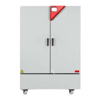
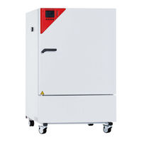
Constant climate chambers with program control
Brand: Binder
|
Category: Climate chamber
|
Size: 10 MB
Table of Contents
Advertisement
Binder KBF 115-UL Service Manual (140 pages)
Constant climate chambers with program control
Brand: Binder
|
Category: Climate chamber
|
Size: 8 MB