Table of Contents
Advertisement
Quick Links
EUROSTER 10M – INSTALLATION AND OPERATION MANUAL 1
CONTROLLER OF A MIXING VALVE ACTUATOR AND A CH PUMP
MANUFACTURER: P.H.P.U. AS, Chumiętki 4, 63-840 Krobia, Poland
1. INTRODUCTION
In order to ensure proper operation of the controller and the CH system, please read this
manual carefully.
2. APPLICATION
Euroster 10M controller is designed to control the heating circuit temperature (e.g., under-
floor heating) using a mixing valve equipped with a 3-point controlled actuator (230 V).
The temperature is controlled using the P.I. (Proportional-Integral) algorithm, which allows
for quick and precise regulation for various loads.
Furthermore, the device activates the CH pump, cooperates with room thermostats and
controls a gas boiler or other heating device.
3. CONTROLLER FUNCTIONS
•
Maintains the preset heating zone temperature
•
Controls the 3-point 230 V actuator of the mixing valve
•
Controls the CH pump of the heating zone
•
Cooperates with a room thermostat
•
Measures the heating source temperature
•
Is equipped with a voltage-free output for activating the heating source
•
Protects the installation against freezing
•
Prevents seizure of the pump and the valve – Anti-Stop function
•
Protects the heating zone against overheating – adjustable alarm temperature of
a controlled zone
•
Temperature reading correction
•
Set of sensors included
•
Installation in an electric cabinet (6 modules) on a DIN 35 mm rail.
•
EUROSTER 10M controller is equipped with an Anti-Stop system that prevents the
process of scale build-up on the unused pump rotor and the mixer. It automatically
turns the pump and the mixer on every 14 days when the heating season is over.
EUROSTER 10M
FEATURING HEATING SOURCE CONTROL
Manual version: 01.08.2023
Advertisement
Table of Contents

Related Manuals for EUROSTER 10M


Summary of Contents for EUROSTER 10M
- Page 1 2. APPLICATION Euroster 10M controller is designed to control the heating circuit temperature (e.g., under- floor heating) using a mixing valve equipped with a 3-point controlled actuator (230 V). The temperature is controlled using the P.I. (Proportional-Integral) algorithm, which allows for quick and precise regulation for various loads.
- Page 2 EUROSTER 10M – INSTALLATION AND OPERATION MANUAL 2 Keep the controller turned on to allow the function to operate after the heating season. 4. VISIBLE ELEMENTS OF THE CONTROLLER 1. Controller’s power connection – 230 V 50 Hz 2. Output for connecting the CH pump 230 V 50 Hz 3.
- Page 3 The controller interacts only with actuators equipped with limit switches. CAUTION! Euroster 10M controller and a heat emitting device are connected to the “Boiler” output and must be powered from the same phase of the power system. a) Connection Diagram...
- Page 4 Most commonly, boilers are equipped with the normally open connection (a jumper must be removed from the heating source), in such cases, you need to connect the 10M controller with COM and NO terminals (the controller has the COM and NO termi- nals).
-
Page 5: Mounting Template
EUROSTER 10M – INSTALLATION AND OPERATION MANUAL 5 6. MOUNTING TEMPLATE The following diagram is simplified and does not cover all the elements necessary for the correct operation of the system. EUROSTER 10M controller Heating zone, e.g. floor heating Heating zone temperature sensor... -
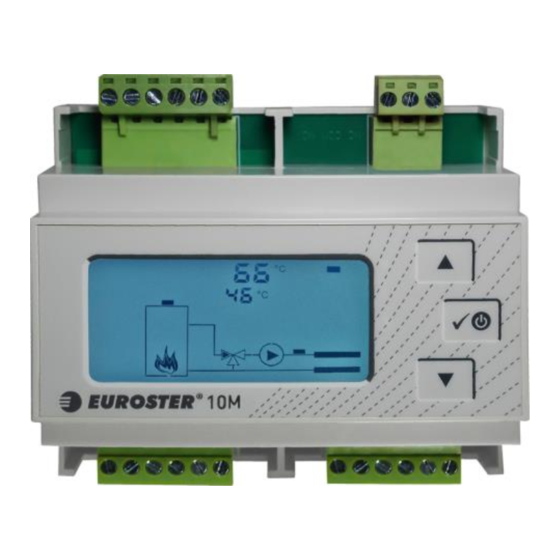
Page 6: Display Description
EUROSTER 10M – INSTALLATION AND OPERATION MANUAL 6 8. DISPLAY DESCRIPTION Active elements of the display are presented below: Name of the set parameter – displayed while previewing or changing param- eters Heating source (boiler) temperature sensor icon Test operation icon – displayed during manual control Alarm icon –... - Page 7 EUROSTER 10M – INSTALLATION AND OPERATION MANUAL 7 The controller configuration is specified below: press buttons to select the desired pa- rameter. The controller will show the value (at the top) and number (at the bottom). In order to change the value of the displayed parameter, press √ (the parameter value starts blinking), set the required value using , and confirm the selection by pressing √.
- Page 8 EUROSTER 10M – INSTALLATION AND OPERATION MANUAL 8 7. Temperature of Supply Alarm Exceeding the alarm temperature on the system’s supply triggers the alarm algo- rithm, which aims to cool down the boiler. The alarm algorithm heats the zone to a temperature close to the alarm threshold.
-
Page 9: Controller Operation
EUROSTER 10M – INSTALLATION AND OPERATION MANUAL 9 Setting Value unit Name Default Min. Max. Temperature of Supply Alarm °C Correction of the boiler °C temperature sensor read-out Correction of the controlled zone °C temperature sensor read-out Mixer operation Pump operation 1) The displayed value is calculated by the controller 2) -1 stands for mixer closure, 1 –... -
Page 10: Troubleshooting
16. SIMPLIFIED DECLARATION OF EU CONFORMITY P.H.P.U. AS AGNIESZKA SZYMAŃSKA-KACZYŃSKA hereby declares that the type of EU- ROSTER 10M equipment conforms to the following directives: 2014/35/EU (LVD), 2014/30/EU (EMC), 2011/65/EU (RoHS). The complete text of the Declaration of EU conformity is available at the following Internet address: www.euroster.pl. -
Page 11: Electronic Waste Management Information
EUROSTER 10M – INSTALLATION AND OPERATION MANUAL 11 19. ELECTRONIC WASTE MANAGEMENT INFORMATION This product is designed and manufactured from high-quality materials and components suitable for reuse. If the equipment, packaging, user manual, etc. is provided with a crossed-out wheelie bin symbol, it means that the product should be selectively collected in accordance with the Directive 2012/19/EU of the European Parliament and of the Council. -
Page 12: Warranty Certificate
EUROSTER 10M – INSTALLATION AND OPERATION MANUAL 12 WARRANTY CERTIFICATE EUROSTER 10M CONTROLLER Warranty terms: 1. The warranty is valid for 24 months from the device's sale date. 2. The claimed module along with this warranty certificate must be supplied to the seller.
Need help?
Do you have a question about the 10M and is the answer not in the manual?
Questions and answers