Table of Contents
Advertisement
Quick Links
UNIVERSAL TIMER
UTR-1033 Manual
TECHNICAL SPECIFICATION
INPUT SPECIFICATION:
NPN/PNP Proximity
Input (Start Pulse)
Micro Switch
Sec (9.99/99.9/999)
Time Range
Min (9.59/99.9/999)
Hour (9.59/99.9/999)
DISPLAY AND KEYS:
Upper: 3 digit, 7 segment, 0.80"
Display
Lower: 3 digit, 7 segment, 0.40"
Keys
SET, SHIFT, INC, ENT/RST
DIMENSION:
Size
96 (H) x 96 (W) x 43 (D) mm
Panel Cutout
92 (H) x 92 (W) mm
GENERAL SPECIFICATION:
Cyclic On Timer
Cyclic Off Timer
Operating Mode
Delay On Timer
Delay Off Timer
Counting Direction
UP/ DOWN
Front Panel Reset
Reset Option
Terminal Reset
OUTPUT SPECIFICATION:
Relay Output
Relay
1 nos.
Relay Type
2 C/O
Rating
5A, 230V AC
AUXILIARY SUPPLY:
Supply voltage
100 to 270V AC, 50-60Hz
Power consumption
Approx 3 VA @ 230V AC MAX
(VA RATING)
ENVIRONMENT CONDITION:
Operating Temp.
0°C to 55°C
UP to 95% RH
Relative Humidity
(non-condensing)
Protection Level
IP-65 (Front side) As per IS/IEC
(AS Per Request)
60529 : 2001
MECHANICAL INSTALLATION
Outline Dimension (mm)
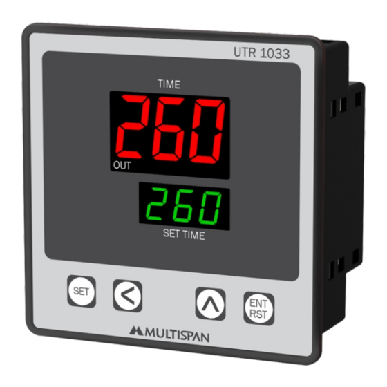
UTR 1033
TIME
260
OUT
96
260
SET TIME
ENT
SET
RST
3
96
TERMINAL CONNECTION
20
19
18
17
MICRO SWITCH:- M/S Connection 6 & 8
Made in India
100
~
270V AC
50/60 HZ
!
4VA
L
N
+12V
1
2
3
4
Panel Cutout
Dimension (mm)
92
92
43
16
15
14 13
12
NO
C
NC
NO
C
Relay
Relay
UTR-1033
www.multispanindia.com
RESET
I/P
I/P
NPN
PNP
GND
5
6
7
8
9
11
NC
10
Page 1
Advertisement
Table of Contents

Related Manuals for MULTISPAN UTR-1033


Summary of Contents for MULTISPAN UTR-1033
- Page 1 UNIVERSAL TIMER AUXILIARY SUPPLY: UTR-1033 Manual Supply voltage 100 to 270V AC, 50-60Hz Power consumption Approx 3 VA @ 230V AC MAX (VA RATING) ENVIRONMENT CONDITION: Operating Temp. 0°C to 55°C UP to 95% RH Relative Humidity (non-condensing) Protection Level...
- Page 2 STATUS LED DESCRIPTION TIMING DIAGRAM Start Pulse CYCLIC ON ON Time OFF Time 1 ON Time OFF Time 1 output indication Time Upto selected Time 1( Time 1( Time 2( Time 2( total no. of repeat Cycle KEY OPERATION CYCLIC OFF FUNCTION PRESS KEY OPERATOR MODE...
- Page 3 PARAMETER SETTING To enter into parameter setting Enter Password 25 Select Operating Mode If Cyclic Mode selected (Cyclic ON) (Cyclic OFF) (Delay OFF) (Delay ON) If Delay ON/OFF Mode selected No. of Repeat Cycle Change by & Unit Selection For Delay Time Unit Selection For Cycle ON Time (Sec/Min/Hr.) Change by...
- Page 4 MECHANICAL INSTALLATION GUIDELINES INSTALLATION GUIDELINES 1. Prepare the panel cutout with proper dimensions as show 1. This equipment, being built-in-type, normally becomes a above. part of main control panel and in such case the terminals 2. Fit the unit into the panel with the help of clamp given. do not remain accessible to the end user after installation and internal wiring.
Need help?
Do you have a question about the UTR-1033 and is the answer not in the manual?
Questions and answers