Table of Contents
Advertisement
Quick Links
DUCTLESS SINGLE-WAY CASSETTE INVERTER++ AIR CONDITIONER / HEAT PUMP SYSTEM
QUANTUM INVERTER SERIES
(CYK-22 ONE-WAY CASSETTE)
OWNER'S AND INSTALLATION MANUAL
Model Numbers Encompassed:
CYK009GMFILCAD
CYK012GMFILCAD
CYK018GMFILCAD
IMPORTANT NOTE:
Read this manual carefully before installing
or operating your new air conditioning system.
Make sure to save this manual for future reference.
© PARKER DAVIS HVAC INTERNATIONAL, INC., ALL RIGHTS RESERVED. REVISION 09-2023
Advertisement
Table of Contents

Related Manuals for Pioneer QUANTUM INVERTER Series


Summary of Contents for Pioneer QUANTUM INVERTER Series
- Page 1 DUCTLESS SINGLE-WAY CASSETTE INVERTER++ AIR CONDITIONER / HEAT PUMP SYSTEM QUANTUM INVERTER SERIES (CYK-22 ONE-WAY CASSETTE) OWNER’S AND INSTALLATION MANUAL Model Numbers Encompassed: CYK009GMFILCAD CYK012GMFILCAD CYK018GMFILCAD IMPORTANT NOTE: Read this manual carefully before installing or operating your new air conditioning system.
-
Page 2: Table Of Contents
Safety Precautions .......................04 Owner’s Manual Unit Speci cations and Features ...................08 1. Unit Parts ...............................08 2. Operating temperature .........................09 .................................10 3. Features ..........................11 4. Energy Saving Tips Care and Maintenance .....................12 Troubleshooting .........................15... - Page 3 Installation Manual Accessories ...........................17 Unit Parts ...........................19 Indoor Unit Installation .......................20 1. Select installation location ........................20 2. Indoor Unit Installation ...........................22 3. Optinal parts installation ........................25 Outdoor Unit Installation ....................27 1. Select installation location ........................27 2. Install drain joint ............................28 3.
-
Page 4: Safety Precautions
Safety Precautions Read Safety Precautions Before Operation and Installation Incorrect installation due to ignoring instructions can cause serious damage or injury. The seriousness of potential damage or injuries is classified as either a WARNING or CAUTION. WARNING CAUTION This symbol indicates the possibility of This symbol indicates the possibility of property damage or serious consequences. - Page 5 WARNINGS FOR PRODUCT USE • Dispose of this unit’s packaging carefully, so children cannot playwith it. Packaging, especially plastic packaging, can be dangerous, can cause serious injury or death. Screws, staples and other metal packaging components can be sharp and should be disposed of carefully to avoid injury. •...
- Page 6 ELECTRICAL WARNINGS • Do not modify the length of the power supply cord or use an extension cord to power the unit. • The product must be properly grounded at the time of installation, or electrical shock may occur. • For all electrical work, follow all local and national wiring standards, regulations, and the Installation Manual.
- Page 7 ELECTRICAL WARNINGS • When moving or relocating the air conditioner, consult experienced service technicians for disconnection and reinstallation of the unit. • How to install the appliance to its support, please read the information for details in "indoor unit installation" and "outdoor unit installation" sections . Page 7 ...
-
Page 8: Unit Speci Cations And Features
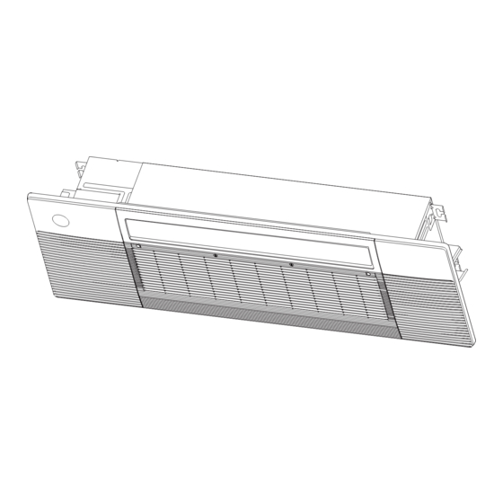
Unit Speci cations and Features Unit Parts NOTE: I llustrations in this manual are for explanatory purposes. The actual shape of your indoor unit may be slightly di erent. The actual shape shall prevail. Air Intake Grille Air Filter Air Vane Display Panel Air Outlet Air Inlet... -
Page 9: Operating Temperature
Display panel The display panel has one type and the appearance of the type is shown in below. “ ” when Electric heating feature is activated (Not available for this unit) “ ” when TIMER is set. “ ” when the unit is on. “... -
Page 10: Features
To further optimize the performance of your unit, do the following: • Keep doors and windows closed. • Limit energy usage by using TIMER ON and TIMER OFF functions. • Do not block air inlets or outlets. • Regularly inspect and clean air lters. Features Refrigerant Leak Detection System Default Setting... -
Page 11: Energy Saving Tips
Active Clean function (Multi-Zone Systems models Lifting panel operation do not have this function) In the stand-by mode, press the “Mode” and The Active Clean Technology washes away “Down” buttons for 3 seconds at the same time, dust when it adheres to the heat exchanger by the remote controller enters the setting panel automatically freezing and then rapidly thawing state, and the remote controller displays "F2". -
Page 12: Care And Maintenance
Care and Maintenance Cleaning Your Indoor Unit WARNING: DO NOT REMOVE OR CLEAN THE FILTER BY YOURSELF BEFORE CLEANING OR MAINTENANCE Removing and cleaning the filter can be REMEMBER TO DISCONNECT THE POWER BEFORE dangerous. Removal and maintenance must CLEANING OR MAINTENANCE, EXCEPT FOR CLEANING be performed by a certified technician. - Page 13 a. Hold the upper edge of the lter with both 3. Clean the air lter hands. Gently turn and lift until the upper edge Dusts will accumulate on the lter along with is free from the wire rope. the unit operation, and need to be removed from b.
- Page 14 CAUTION Maintenance – Long Periods of Non-Use If you plan not to use your air conditioner for an • Before changing the lter or cleaning, turn o the unit . extended period of time, do the following: • When removing lter, do not touch metal parts in the unit.
-
Page 15: Troubleshooting
Troubleshooting SAFETY PRECAUTIONS If any of the following conditions occurs, turn o your unit immediately! • The power cord is damaged or abnormally warm. • You smell a burning odor. • The unit emits loud or abnormal sounds. • A power fuse blows or the circuit breaker frequently trips. •... - Page 16 Issue Possible Causes The outdoor unit The unit will make di erent sounds based on its current operating mode. makes noises Dust is emitted from The unit may accumulate dust during extended periods of non-use, which will be either the indoor or emitted when the unit is turned on.
-
Page 17: Accessories
Problem Possible Causes Solution Power failure Wait for the power to be restored The power is turned o Turn on the power The unit is not The fuse is burned out Replace the fuse working The Unit’s 3-minute protection Wait three minutes after restarting has been activated the unit Turn timer o... - Page 18 Accessories Name Shape Q‘ty(pc) Cable tie Drainpipe adaptor Screw kits (ST8*50 , M4*22 , ST3.9*16 , ST4.8*12,ST3.9*10) (8,8,2,2,3) Water receiver Seal Drain joint Wire controller (optional) Rubber ring WiFi controller (optional) Panel Copper nut Note Name Shape Q‘ty(pc) Liquid side Φ...
-
Page 19: Unit Parts
Unit Parts NOTICE NOTICE The installation must be performed in accordance with the requirement of local and national standards. The installation may be slightly di erent in di erent areas. Air-break switch ③ ④ ② ① ⑤ ⑥ ⑦ ⑦ ⑧... -
Page 20: Indoor Unit Installation
Indoor Unit Installation The ceiling is horizontal and its structure can √ NOTICE NOTICE sustain the weight of the indoor unit. Panel installation should be performed after The air inlet and outlet are not blocked. √ wiring and piping have been completed. The air ow can ll the entire room. - Page 21 Installation place (unit: mm/inch) Wall Ceiling >200mm(7.87 in) air inlet air outlet Ceiling hole Indoor parts installation size (unit: mm/inch) 423mm (16.65in) 335mm(13.19in) 1105mm(43.5in) 1360mm(53.54in) Page 21 ...
-
Page 22: Indoor Unit Installation
Step 2: Indoor Unit Installation Make sure that only speci ed components are Connect the wire to the air breaker according used for the installation works. ● to the wire connecting diagram. 1. Connect wire to indoor air handler Model A: with circuit breaker Remove the four screws to open the indoor ●... - Page 23 Fasten and x the wire body with a tie. Model B: with terminal ● Remove the four screws to open the indoor ● control box and terminal box. Four screws Fasten and x the wire body with a tie Install the circuit breaker cover by xing the ●...
- Page 24 Connect the wire to the terminal according to Install the terminal cover by xing the two screws. ● ● the wire connecting diagram. Two screws Select one to connect ground wire 2. Install the indoor air handler Fix the wire with the clip by using the two screws. ●...
-
Page 25: Optinal Parts Installation
Step 3: Optional parts Installation Align the refrigerant pipes, drain pipeswith their ● Wire controller connection points before mounting the unit. Mount the indoor unit with at least two people For the function introduction, operation to lift and secure it then x the unit body to the instruction and installation, please refer to the roof beam by using 6×... - Page 26 Connecting the wire from the control box. ● NOTICE WARNING To CCM TO 485 WIRE TO 2 WIRE CONTROLLER Wire-controller Comm.Bus Please follow local regulations and take MAGNETIC RING CN41 is a measures to isloate high voltage and low voltage. customised part.
-
Page 27: Outdoor Unit Installation
Outdoor Unit Installation Page 27 ... -
Page 28: Install Drain Joint
Page 28 ... - Page 29 Page 29 ...
- Page 30 If you are installing the outdoor unit on the ground,or a concrete mounting platform,use the following steps: 1.Mark the positions for four expansion bolts based on dimensions in the Mounting Dimensions chart and illustrations above. 2.Pre-drill holes for expansion bolts. 3.Clean concrete dust away from the holes.
-
Page 31: Drainpipe Installation
Drainpipe Installation The drainpipe is used to drain water away from NOTE ON DRAINPIPE INSTALLATION the unit. Improper installation may cause unit • When using an extended drainpipe, tighten and property damage. the indoor connection with an additional protection tube to prevent it from pulling loose. - Page 32 Drill wall hole 0-53cm 1. Using a 65mm (2.5in) or 90mm(3.54in) (20.8”) (depending on models )core drill, drill a hole in the wall. Make sure that the hole is drilled at a slight downward angle, so ≥10cm that the outdoor end of the hole is lower (4”) than the indoor end by about 5mm to 7mm (0.2-0.275in).
-
Page 33: Refrigerant Piping Connection
Page 33 ... - Page 34 Page 34 ...
- Page 35 (180-200kgf.cm) 32-39 N.m (320-390kgf.cm) 49-59 N.m (490-590kgf.cm) 57-71 N.m (570-710kgf.cm) 67-101 N.m (670-1010kgf.cm) 85-110 N.m (850-1100kgf.cm) 6.After connecting the copper pipes to the indoor unit,wrap the power cable , signal cable and the piping together with binding tape. 7.Thread this pipeline through the wall and connect it to the outdoor unit.
-
Page 36: Electrical Connections
Electrical Connections Page 36 ... - Page 37 (Some indoor unit come with their own) (Some indoor unit come with their own) (Some indoor unit come with their own) Page 37 ...
- Page 38 Page 38 ...
- Page 39 Page 39 ...
-
Page 40: Air Evacuation
Page 40 ... - Page 41 Liquid Side Diameter Refrigerant Φ 6.35( 1/4in) Φ 9.52( 3/8in) Φ 12.7( 1/2in) (Total pipe length- (Total pipe length- (Total pipe length- R410A: standara pipe length) standara pipe length) standara pipe length) (ori ce tube in the indoor unit): ×65g(0.69oz)/m(ft) ×115g(1.23oz)/m(ft) ×30g(0.32oz)/m(ft) (Total pipe length-...
-
Page 42: Electrical And Gas Leak Chechs
Electrical and Gas leak Checks Gas Leak Checks gaseous leaks. Use Fig. 8.1 below as a guide for the critical points to check for leaks. Soap and Water Method Using a soft brush or spray bottle, apply a soapy water solution to all of the pipe connection points of WARNING –... -
Page 43: Panel Installation
Panel Installation ST3.9*16 screw Step1 Prepare and install ceiling Drill 430 mm x 1300 mm( 16.93’’x51.18’’ ) ● hole into the ceiling based on the layout of the installation board. The centre of the ceiling opening should M4*22 screw match the centre of the body of the indoor NOTICE unit. - Page 44 Pull the panel grille out of the panel, x the Install the control box cover and turn the ● ● cassette panel to the one-way cassett by two circuit breaker to ON, then close the two plastic plastic buckles. covers on both sides of the panel. palstic buckle Manually rotate the air de ector, x the panel ●...
-
Page 45: Optinal Parts Installation
Step 3 Optinal parts installation Connect the display board to the main control ● board, up to four wires are required to connect. Wireless module NOTICE NOTICE Wireless module, or named smart kit, if you choose this con guration, please follow the The corresponding colors or corresponding steps below to install. -
Page 46: Test Run
Open the front panel and insert the wireless CAUTION ● module (smart kit) into the reserved interface. Failure to perform the test run may result in 5 core unit damage, property damage, or personal injury. Test Run Instructions 1. Open both the liquid and gas stop valves. 2. - Page 47 Water Discharge Test • Before the test, make sure that the water discharge pipeline is smooth, and check that each connection is sealed properly. • Conduct the water discharge test in the new room before the ceiling is paved. 1. Connect the power supply, and set the air conditioner to operate in the cool mode. Check the running sound of the drainage pump.
- Page 48 : (305) 513-4488 : (305) 513-4499 E-mail : info@pdhvac.com Website: www.pdhvac.com Pioneer product line, parts, and supplies are available online for convenient ordering at: https://www.highseer.com https://www.pioneerminisplit.com Scan the below code to visit our support page where you can find more installation materials:...
Need help?
Do you have a question about the QUANTUM INVERTER Series and is the answer not in the manual?
Questions and answers