Advertisement
Quick Links
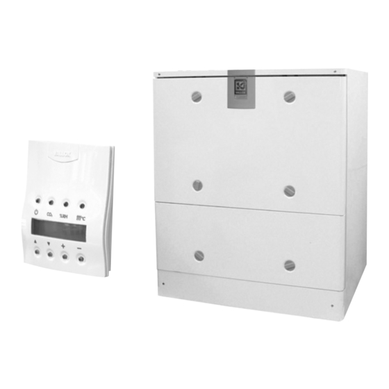
Vallox
DigitSED
ELECTRONIC CONTROLLER
WITH LCD DISPLAY
MLV = heating/cooling radiator
VKL = water-circulating radiator
Vallox 200 SE electric/electric
Product IDs
Vallox 200 SE electric/electric L
Vallox 200 SE electric/electric R
Air volumes Supply air
Extract air
Electrical connection
Degree of protection provided
by enclosures
Post-heating radiator
Preheating radiator
Additional heating radiator
Fans
Supply air
Extract air
Efficiency
Annual efficiency
Supply air efficiency
Specific Fan Power SFP
Filters
Supply air
Extract air
Heat recovery bypass
Weight
Comes standard with control
VALLOX 200 SE MLV/electric
Product IDs
Vallox 200 SE MLV/electric L
Vallox 200 SE MLV/electric R
Air volumes Supply air
Extract air
Electrical connection
Degree of protection provided
by enclosures
Post-heating radiator
Preheating radiator
Additional heating radiator
Fans
Supply air
Extract air
Efficiency
Annual efficiency
Supply air efficiency
Specific Fan Power SFP
Filters
Supply air
Extract air
Heat recovery bypass
Weight
Comes standard with control
© Vallox • We reserve the right to make changes without prior notice.
Vallox
200
Vallox code
3527800
3527900
3
190 dm
/s, 100 Pa
3
220 dm
/s, 100 Pa
230 V, 50 Hz, 15.2 A fixed mounting
IP34
Electric, 1 kW, 4.3 A
Electric, 2 kW, 8.7 A
-
2 x 117 W 0.9 A EC
2 x 117 W 0.9 A EC
60% B
84 %
3
1.3 (125 dm
/s) B
G4 + F7
G4
Automatic
146 kg
Vallox Digit SED controller
Vallox code
3543900
3544000
3
180 dm
/s, 100 Pa
3
220 dm
/s, 100 Pa
230 V, 50 Hz, 6.5 A fixed mounting
IP34
Electric, 1 kW, 4.3 A
MLV heating/cooling radiator
-
2 x 117 W 0.9 A EC
2 x 117 W 0.9 A EC
60% B
84 %
3
1.3 (125 dm
/s) B
G4 + F7
G4
Automatic
146 kg
Vallox Digit SED controller
SE
Vallox 280 SE electric/VKL
Product IDs
Vallox 280 SE electric/VKL L
Vallox 280 SE electric/VKL R
Air volumes Supply air
Extract air
Electrical connection
Degree of protection provided
by enclosures
Post-heating radiator
Preheating radiator
Additional heating radiator
Fans
Supply air
Extract air
Efficiency
Annual efficiency
Supply air efficiency
Specific Fan Power SFP
Filters
Supply air
Extract air
Heat recovery bypass
Weight
Comes standard with control
VALLOX 200 SE MLV/VLK
Product IDs
Vallox 200 SE MLV/VKL L
Vallox 200 SE MLV/VKL R
Air volumes Supply air
Extract air
Electrical connection
Degree of protection provided
by enclosures
Post-heating radiator
Preheating radiator
Additional heating radiator
Fans
Supply air
Extract air
Efficiency
Annual efficiency
Supply air efficiency
Specific Fan Power SFP
Filters
Supply air
Extract air
Heat recovery bypass
Weight
Comes standard with control
• 1.09.280b ENG
• Updated
24.9.2015
• Valid from
24.9.2015
• Type 3486
© Vallox
Vallox code
3528000
2528100
3
175 dm
/s, 100 Pa
3
220 dm
/s, 100 Pa
230 V, 50 Hz, 10.9 A fixed mounting
IP34
VKL water-circulating radiator, 3 kW
Electric, 2 kW, 8.7 A
-
2 x 117 W 0.9 A EC
2 x 117 W 0.9 A EC
60% B
84 %
3
1.3 (125 dm
/s) B
G4 + F7
G4
Automatic
146 kg
Vallox Digit SED controller
Vallox code
3544100
3544200
3
165 dm
/s, 100 Pa
3
220 dm
/s, 100 Pa
230 V, 50 Hz, 2.2 A fixed mounting
IP34
VKL water-circulating radiator, 3 kW
MLV heating/cooling radiator
-
2 x 117 W 0.9 A EC
2 x 117 W 0.9 A EC
60% B
84 %
3
1.3 (125 dm
/s) B
G4 + F7
G4
Automatic
146 kg
Vallox Digit SED controller
Advertisement

Subscribe to Our Youtube Channel
Related Manuals for Vallox 3527800


Summary of Contents for Vallox 3527800
- Page 1 Automatic Heat recovery bypass Automatic Weight 146 kg Weight 146 kg Comes standard with control Vallox Digit SED controller Comes standard with control Vallox Digit SED controller © Vallox • We reserve the right to make changes without prior notice.
- Page 2 - Control panel - CO sensor Supply liquid to the - LON converter MLV unit Feed cable Return liquid from Distribution panel the MLV unit © Vallox • We reserve the right to make changes without prior notice.
- Page 3 (10 m sound absorption) ADJUSTMENT POSITION/AIR FLOWS (supply/extract) Vallox 200 SE 78/97 l/s 114/134 l/s 154/172 l/s 191/202 l/s electric/electric , dB(A) © Vallox • We reserve the right to make changes without prior notice.
- Page 4 (10 m sound absorption) ADJUSTMENT POSITION/AIR FLOWS (supply/extract) Vallox 200 SE 78/97 l/s 114/134 l/s 154/172 l/s 191/202 l/s electric/VKL , dB(A) © Vallox • We reserve the right to make changes without prior notice.
- Page 5 (10 m sound absorption) ADJUSTMENT POSITION/AIR FLOWS (supply/extract) Vallox 200 SE 78/97 l/s 114/134 l/s 154/172 l/s 191/202 l/s MLV/electric , dB(A) © Vallox • We reserve the right to make changes without prior notice.
- Page 6 (10 m sound absorption) ADJUSTMENT POSITION/AIR FLOWS (supply/extract) Vallox 200 SE MLV/VKL 78/97 l/s 114/134 l/s 154/172 l/s 191/202 l/s , dB(A) © Vallox • We reserve the right to make changes without prior notice.
- Page 7 ADJUSTMENT POSITION/AIR FLOWS (supply/extract) VALLOX 200 SE + SILENCER PART 70/77 102/107 135/135 166/166 L p A, dB(A) L p A = A-painotettu äänenpainetaso (10 m :n äänenabsorptio) © Vallox • We reserve the right to make changes without prior notice.
- Page 8 VALLOX DIGIT SED CONTROL PANEL Control Vallox 200 SE can be controlled with the control panel delivered with the unit (3 control panels at most) and with optional CO sensors (5 at most) and %RH sensors (2 at most). Fan speeds of the unit can be controlled via remote monitoring with a voltage signal.
- Page 9 3 = orange 2 4 = white 2 5 = metal = signal ground Base plate of the CO sensor Electronics card of the CO sensor (model may vary) © Vallox • We reserve the right to make changes without prior notice.
- Page 10 TZ2 = OVERHEAT PROTECTOR + 95° (RESETTABLE) PDS1 = PRESSURE DIFFERENCE SWITCH FOR THE SUPPLY AIR DUCTWORK (OPTION) PDS2 = PRESSURE DIFFERENCE SWITCH FOR THE EXTRACT AIR DUCTWORK 7018900C (OPTION) © Vallox • We reserve the right to make changes without prior notice.
- Page 11 NOTE! When the fans of the VALLOX 200 SE unit are controlled via remote monitoring control, the loop between VAK S and VAK GND is detached. FAULT FAULT BOOST SWITCH Solenoid valve Circulation pump © Vallox • We reserve the right to make changes without prior notice.
- Page 12 10.0 0.04 0.06 0.08 0.10 Temperature of geothermal liquid coming to radiator °C Temperature of geothermal liquid coming to radiator °C Liquid flow dm Liquid flow dm © Vallox • We reserve the right to make changes without prior notice.
- Page 13 0.020 dm Air flow Air flow 160 dm 160 dm 120 dm 120 dm 80 dm 80 dm Temperature difference of water °C Temperature difference of water °C © Vallox • We reserve the right to make changes without prior notice.
- Page 14 VALLOX 200 SE HEATING, VKL WATER RADIATOR VKL WATER RADIATOR PRESSURE LOSS IN WATER CIRCULATION Defined for 100% water 0.01 0.02 0.03 0.04 0.06 0.08 Water flow © Vallox • We reserve the right to make changes without prior notice.
- Page 15 DIFFERENCE CARBON DIOXIDE SENSOR (5 AT MOST) SWITCH CONTROL PANEL (3 AT MOST) HUMIDITY SENSOR (2 AT MOST) PREHEATING PDS2 TZ1 TZ2 UNIT, LP1 ELECTRIC VENTILATION ZONE © Vallox • We reserve the right to make changes without prior notice.
- Page 16 LP2. If surface temperature exceeds the threshold, overheat protection is triggered and power supp- ly to the heating unit is stopped. Overheat protector TZ1 is reset automatically and TZ2 manually. © Vallox • We reserve the right to make changes without prior notice.
- Page 17 PRESSURE DIFFERENCE CARBON DIOXIDE SENSOR (5 AT MOST) SWITCH PRESSURE CONTROL PANEL (3 AT MOST) DIFFERENCE SWITCH HUMIDITY SENSOR (2 AT MOST) PDS2 UNIT LIQUID VENTILATION ZONE © Vallox • We reserve the right to make changes without prior notice.
- Page 18 The fans restart automatically as soon as the risk of freezing passes (supply air > 10 °C). Water radiator control valve Included in LP2 (water) Solenoid valve (Not included in the delivery) Circulation pump (Not included in the delivery) © Vallox • We reserve the right to make changes without prior notice.
-
Page 19: Installation Instructions
(p. 3-6) show volume air flows at various adjustment positions. • The red measurement hose is on the pressure side and the black hose on the suction side of the fan. © Vallox • We reserve the right to make changes without prior notice. -
Page 20: Pipe Connections
• The screw-type coupling is located almost in the middle of the unit. This is why the unit has to be mounted level with the horizontal. Location of condensing water connection © Vallox • We reserve the right to make changes without prior notice. - Page 21 Note! Because of the risk of humidity damage, supply air temperature in a duct with no condensation insulation should not go below +16...20 °C. © Vallox • We reserve the right to make changes without prior notice.
- Page 22 Note! Because of the risk of humidity damage, supply air temperature in a duct with no condensation insulation should not go below +16...20 °C. GROUND COLLECTOR © Vallox • We reserve the right to make changes without prior notice.
-
Page 23: Installation
Vallox 200 SE, and connect them • If Vallox 200 SE is equipped with a water-circulating heater and/or MLV unit, you should always detach the to the heating unit. (See the adjoining figure.) lamellar silencer plate of the supply air duct. - Page 24 Vallox Oy Myllykyläntie 9-11 32200 Loimaa FINLAND +358 10 7732 200 © Vallox • We reserve the right to make changes without prior notice.
Need help?
Do you have a question about the 3527800 and is the answer not in the manual?
Questions and answers