
Related Manuals for Vallox 3756


Summary of Contents for Vallox 3756
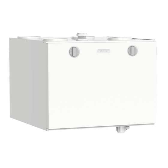
- Page 1 Model Document Vallox 99 MV CF D11218 Type Valid from 3756 01.01.2022 Updated 02.02.2023 Manual Ventilation unit...
-
Page 2: Table Of Contents
MyVallox of the Vallox Silent Klick siphon ......9... -
Page 3: Safety
INTENDED USE allowed to play with the device. All Vallox ventilation units have been designed to provide appropriate and continuous ventilation so as to present no threat to health and to maintain structures in good condition. IMPORTANT... -
Page 4: Safety Signs Used In The Instructions
INSTALLATION OPTIONS NOTE The standard equipment and • Vallox 99 MV can be mounted either on the wall, or on the ceiling available accessories by using a mounting plate (optional). vary from country to country. SYSTEM DESCRIPTION Internet 2. -
Page 5: Ventilation Unit Control
NOTE For the MyVallox Cloud/Home Ventilation unit control options. instructions, please go to techmanuals.info/ Operation of the Vallox ventilation unit can be controlled by the ValloxMV/ENG/help/ following means: webhelp • Through the My Vallox Control panel installed in the building. -
Page 6: Main Parts
MAIN PARTS R model in the figure Extract air fan Additional heating resistor Supply air fan Safety switch Fine filter for supply air Internal carbon dioxide and humidity sensor Heat recovery cell Ceiling bushing for electric wires Bypass damper of the HR cell Control panel Coarse filter for supply air Carbon dioxide sensor (optional) -
Page 7: Installation
Make sure that the unit is horizontally level after mounting. MOUNTING ON THE CEILING Vallox 99 MV can be equipped with an optional ceiling mounting plate. To attach the ceiling mounting plate: • On rafter frames or other frame structure with M8 thread bars so NOTE that they withstand the weight of the unit. -
Page 8: Installing The Ventilation Unit To The Ceiling Mounting Plate
Installing the ventilation unit to the ceiling mounting plate Install the ceiling mounting plate with M8 thread bars so that it is horizontally level. NOTE The end of the thread bars must be 5 mm or less below the fastening nut. Do not fasten the ceiling mounting plate too tight to the ceiling. -
Page 9: Removal Of Condensing Water
Space required by the alternative Vallox Silent Klick siphon installation method (elbow) MEASURING AND ADJUSTING THE AIR FLOWS OF THE VENTILATION UNIT The accessories delivered with the unit include four (4) air flow measuring tubes. -
Page 10: Dimensions And Duct Outlets
DIMENSIONS AND DUCT OUTLETS Main parts Dimensions and duct outlets Dimensions R model in the figure. In the L model, the parts are mirrored 8. Post-heating resistor 1. Extract air fan in front of the supply air fan 2. Supply air fan 9. -
Page 11: Maintenance
To replace the filters: Disconnect the ventilation unit from the mains electricity supply. 2. Open the door of the Vallox ventilation unit by undoing the finger screws. Using original Vallox 3. Lift the door off. filters ensures that 4. -
Page 12: Cleaning The Heat Recovery Cell
To check and clean the heat recovery cell: damaged. Disconnect the ventilation unit from the mains electricity supply. 2. Open the door of the Vallox ventilation unit by undoing the finger screws. 3. Lift the door off. CAUTION The door is heavy. -
Page 13: Cleaning The Fans
To clean the fan: Disconnect the ventilation unit from the mains electricity supply. 2. Open the door of the Vallox ventilation unit by undoing the finger screws. 3. Lift the door off. CAUTION The door is heavy. -
Page 14: Cleaning Of The Anemometer
Cleaning of the anemometer The anemometer in the fan must be cleaned at least every three (3) years. It is recommended to use compressed air for the cleaning. CAUTION When using compressed air, the arms of the anemometer must not be allowed to rotate freely. This could damage the bearings. -
Page 15: Technical Specifications
, dB , dB(A) Sound pressure level coming through the envelope of the unit in the room in which it is installed (10m² sound absorption) Adjustment position Adjustment position (%) , dB (A) © Vallox Oy - All rights reserved... -
Page 16: Internal Electrical Connection
INTERNAL ELECTRICAL CONNECTION 230V 50Hz MB_A MB_A MB_B MB_B +24V +24V RS_A RS_A RS_B RS_B TESTER +24V +24V RS_A RS_A RS_B RS_B +11V1 +24V AN/I D/I1 +24V RM/I %RH CO2 RM/O D/I2 1 2 3 4 5 6 130°C 90°C 130°C 90°C Motherboard... -
Page 17: External Electrical Connection
MyVallox CO 2 sensor 1.2W RS_A Local hardware Modbus A signal RM/I 24V relay input RS_B Local hardware Modbus B signal RM/O 24V relay output MyVallox VOC sensor External temperature sensor connector Voltage 24 VDC © Vallox Oy - All rights reserved... -
Page 18: External Electrical Connection For Controlling The Mlv Duct Radiator
EXTERNAL ELECTRICAL CONNECTION FOR CONTROLLING THE MLV DUCT RADIATOR Distribution 24 VDC relay/contactor board for controlling the pump and solenoid valve +24VDC External temperature sensor NTC 4K7 Ethernet MLV control connection on top of the unit VENTILATION UNIT INTERNAL ELECTRICAL CONNECTION RJ45 Female Plug connection 1.2 m on top of the unit... -
Page 19: Duct Radiator Operation
The temperature of the external sensor can be read from the service menu: menu > service menu > unit information page 5 ”External sensor”. © Vallox Oy - All rights reserved... -
Page 20: Duct Radiator Operation Chart
Feed from the distribution board External electrical junction box for the MV Air extraction External NTC sensor for Vallox MV ventilation units Duct radiator (reverse connection) 24 VDC relay/contactor for controlling the pump and the solenoid valve. Not included in the delivery. -
Page 21: Exploded View And Parts List
4114303 Safety switch 948377 949111 cell (optional) Siphon Vallox Silent MyVallox VOC sensor 3494701 Motherboard 949032-1 949112 Klick (optional) Glass tube fuse 63mA Door 4116174 952490 Plastic screw Vallox 99 950308 slow 5x20mm © Vallox Oy - All rights reserved... -
Page 22: Conformity Certificates
CONFORMITY CERTIFICATES... - Page 23 © Vallox Oy - All rights reserved...
- Page 24 Vallox Oy | Myllykyläntie 9-11 | 32200 LOIMAA | FINLAND...
Need help?
Do you have a question about the 3756 and is the answer not in the manual?
Questions and answers