Table of Contents
Advertisement
Quick Links
RR 50 CC ENDURO / ENDURO STD / MOTARD /
MOTARD STD / FACTORY / TRACK
Thanks for you preference, and have a good time! This hand-
book contains the information you need to properly operate and
maintain your motorcycle.
The data and specifi cations provided in this manual does not constitute an
engagement on the part of BETAMOTOR S.p.A. BETAMOTOR reserves the
right to make any changes and improvements to its models at any moment
and without notice.
GB
1
Advertisement
Chapters
Table of Contents

Subscribe to Our Youtube Channel
Related Manuals for Beta RR 50 CC ENDURO


Summary of Contents for Beta RR 50 CC ENDURO
- Page 1 RR 50 CC ENDURO / ENDURO STD / MOTARD / MOTARD STD / FACTORY / TRACK Thanks for you preference, and have a good time! This hand- book contains the information you need to properly operate and maintain your motorcycle.
- Page 2 • check that the plastics are properly fastened • engine bolts • shock absorber bolts/swingarm • wheel hubs/spokes • rear frame • pipe connections • tensioning the chain IMPORTANT For any servicing requirements, please get in contact with Beta- motor’s authorized service network.
-
Page 3: Table Of Contents
Operating instructions ................5 Ecologic guide..................5 Riding safety ..................6 CHAPTER 1 GENERAL INFORMATION ..........7 Vehicle identifi cation data ................ 8 Familiarizing with your vehicle ..............9 Controls ....................10 Digital RPM indicator operating instructions ..........12 Keys ....................18 Steering lock .................. - Page 4 CHAPTER 6 TROUBLESHOOTING ............ 45 Troubleshooting ..................46 INDEX ....................47...
-
Page 5: Operating Instructions
OPERATING INSTRUCTIONS • The vehicle must be accompanied by: number-plate, registration document, tax disc and insurance. • Do not carry animals, pets or loose objects that can stick out from the vehicle. • Riding without a crash helmet is forbidden. •... -
Page 6: Riding Safety
RIDING SAFETY • Observe the Highway Code. • Always put on and fasten a homologated helmet. • Always ride with the low beam on. • Always keep the crash helmet visor clean. • Avoid wearing garments with hanging ends. • Do not keep sharp or brittle objects in your pockets while riding. •... -
Page 7: Chapter 1 General Information
CONTENTS CHAPTER 1 GENERAL INFORMATION Vehicle identifi cation data Familiarizing with your vehicle Controls Digital RPM indicator operating instructions Specifi cations Wiring diagram Recommended lubricants and liquids... -
Page 8: Vehicle Identification Data
VEHICLE IDENTIFICATION DATA FRAME IDENTIFICATION Frame identifi cation data A are stamped on the right side of the steering head tube. ENGINE IDENTIFICATION Engine identifi cation data B are stamped on the l.h. side half crankcase. WARNING: Tampering with the identifi cation numbers is severely punished by law. -
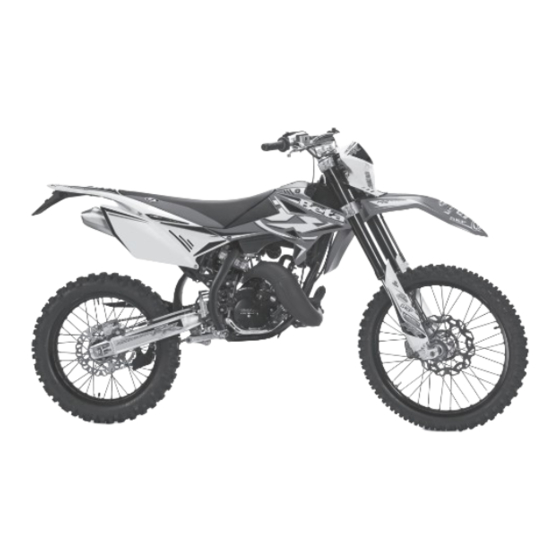
Page 9: Familiarizing With Your Vehicle
FAMILIARIZING WITH THE VEHICLE Main parts: 8 Muffl er 1 Tank cap 9 Silencer 2 Air fi lter 10 Mixer oil tank cap 3 Side stand (not fi tted on Factory version) 4 Fuel cock 5 Fuel tank 6 Radiator cap 7 Kick-starter... -
Page 10: Controls
CONTROLS CLUTCH LEVER The clutch lever 1 is located on the left side of the handlebar. See the Adjustments chapter to adjust. STARTER The starter lever 2 is located on the left side of the handlebar. Turn the lever counter- clockwise to operate. - Page 11 GEARCHANGE LEVER Gearchange lever A is fi tted to the left side of the engine. The positions corresponding to the different gears are shown in the fi gure. BRAKE PEDAL Brake pedal 9 is located in front of the right-hand footrest. KICKSTART The kick-starter pedal 10 is located on the right side of the engine.
-
Page 12: Digital Rpm Indicator Operating Instructions
DIGITAL RPM INDICATOR OPERATING INSTRUCTIONS Series RR 50 Enduro - Enduro standard - Factory - Motard - Motard standard - Track CONTENTS 1 GENERAL SPECIFICATIONS AND GENERAL INFORMATIONS 1.1 General specifi cations 1.2 General informations 2 SETTING THE PARAMETERS 2.1 Setup sequence 2.1.1 Selecting the unit of measure 2.1.2 Selecting the wheel size 2.1.3 Selecting the clock format... -
Page 13: Setting The Parameters
Using only the internal battery: • With the LO symbol, the backlighting will not switch on. The symbol appears when the battery voltage is lower than 2.45V. Reset Button: Using the Reset button, located on the back of the instrument, all travel data will be deleted, including date and time. -
Page 14: Setup Sequence
2.1 SETUP SEQUENCE Select unit of measure Wheel size Clock format Setting the Time Maintenance reminder 2.1.1 Selecting the unit of measure (Km/h or M/h): TO SELECT THE UNIT OF MEASURE (Km/h or M/h), PRESS THE RIGHT OR LEFT BUTTON. WAIT 5 SECONDS TO PROCEED TO THE NEXT SETTING. -
Page 15: Screens
3 SCREENS Switching between 3 normal modes All of the information that the instrument is capable of providing is displayed on one of these 3 screens. The instrument will stay on the set screen until a button is pressed to switch to another screen. -
Page 16: Speedometer
5 SPEEDOMETER Speed The speed is displayed in the centre of screens 1 or 2 and can range from 0 to 399.9 km/h or M/h. The unit of measure (km/h or M/h) appears next to the speed reading. Maximum (Max) and Average (AVG) speed The Maximum (MAX) or Average (AVG) speeds are displayed on screen 3 to the left of the display. -
Page 17: Warning Lights
Travelled distance (DST) The travelled distance can range from 0 to 9999.9 miles or kilometers and appears on the right side of screen 1. To clear the travelled distance, hold the right button down for 5 seconds. Note: you must be on screen 1 to clear the travelled distance. Travelled distance 2 (DST 2) Travelled distance 2 can range from 0 to 9999.9 miles or kilometers and appears on the right side of screen 2. -
Page 18: Keys
KEYS The vehicle is supplied with two keys (one key and its spare), each of which can be used for the steering lock switch, for switching the engine on and off and the refuelling door. - Turn the key to to start up the engine. - Page 19 TECHNICAL DATA dry weight (all models) ..............85 kg VEHICLE DIMENSIONS Version ENDURO MOTARD/ FACTORY STANDARD MOTARD TRACK STANDARD Maximum 2085 2000 2085 2052 2000 length [mm] Maximum width [mm] Maximum height 1225 1155 1225 1190 1155 from ground [mm] Clearance from ground [mm] Saddle height [mm]...
-
Page 20: Specifi Cations
MOTARD/MOTARD STANDARD/TRACK Front tyre Rear tyre Dimension Pressure [Bar] Dimension Pressure [Bar] 100/80 - 17 or 130/70 - 17 or 100/80-17 TL 130/70-17 TL FILLING CAPACITY fuel tank..................6 liters including reserve of................1 liter cooling circuit liquid All the models ................500cc FACTORY .................. - Page 21 REAR SUSPENSION Version ENDURO STD/MOTARD/ FACOTRY ENDURO MOTARD STANDARD/TRACK spring (k) [Kg/mm] 12,5 Length (spring in its seat) [mm] Click in compression (from fully closed) Click in extension (from fully closed) FRONT BRAKE disk-type with hydraulic control Ø 260 mm REAR BRAKE disk-type with hydraulic control Ø...
- Page 22 ENGINE RR 50 type ..............single-cylinder, two-stroke bore x stroke ................. 40,3x39 mm displacement (cm ) ..............49,7 cm compression ratio ................12:1 liquid cooled ignition .............. electronic MORIC - 120W kick-starter spark plug ................NGK BR9 ES clutch .................. wet, multidisc gearchange ................
- Page 23 FUEL SYSTEM RR 50 Version Homologated Competition* Carburetor type DELL’ORTO PHBN 16 HS Main jet Slow jet Start jet Needle Needle position 2° 2° (from top) Air screw turns 1+1/2 1+1/2 (from fully closed) * - Such modifi cation makes the vehicle non-compliant with the road regulations in force.
-
Page 24: Wiring Diagrams Rr 50
ELECTRICAL DIAGRAM RR 50... - Page 25 LEGND ELECTRICAL DIAGRAM RR 50 KEY SWITCH OIL PILOT LAMP NEUTRAL INDICATOR LIGHT HIGH BEAM WARNING LIGHT DIRECTION INDICATOR WARNING LIGHT WHEEL REVOLUTION SENSOR HEADLAMP (DOUBLE FILAMENT BULB) SIDE/TAILLIGHT BULB 12V - 5W ENGINE STOP BUTTON HORN BUTTON HEADLIGHT SELECTOR TURN SIGNAL LAMPS SWITCH L.H.
-
Page 26: Recommended Lubricants And Liquids
RECOMMENDED LUBRICANTS AND LIQUIDS For better operation and longer vehicle life, we advise you to use the products listed in the following chart: TYPE OF PRODUCT TECHNICAL SPECIFICATION TRANSMISSION OIL PANOLIN GEAR BLEND 10W/30 OIL FOR MIXTURE PANOLIN OFF ROAD 2T RACE BRAKE OIL DOT 4 OLIO PER FORCELLE:... -
Page 27: Chapter 2 Operation
CONTENTS CHAPTER 2 OPERATION Checks and maintenance before and after use Running-in Refuelling Starting and stopping the engine... -
Page 28: Checks And Maintenance Before And After Use
CHECKS AND MAINTENANCE BEFORE AND AFTER USE In order to avoid problems connected to the operation of the vehicle, it is advisable to perform a number of checks and maintenance operations before and after use. Just a few minutes given to these procedures will save you time and money, and will make riding much safer. -
Page 29: Refuelling
FUELING The cover A must be unlocked with the ap- propriate key and lifted in order to access the fuel tank’s cap. Remove cap B. The fuel tank will hold approxi- mately 6 liters, 1 liters of which is reserve. Breather pipe C is designed to allow the outfl... -
Page 30: Starting The Engine
STARTUP (only with kickstarter) - Open fuel tank valve A closed open reserve - Check that the gears are in neutral - Position the key to (see page 18). - Depress the kick-starter with a sharp move- ment of the foot and slightly turn the gas control. -
Page 31: Chapter 3 Checks And Maintenance
CONTENTS CHAPTER 3 CHECKS AND MAINTENANCE Gearbox oil Brake pump oil Air fi lter Spark plug Front brake Rear brake Coolant Operations after cleaning Scheduled maintenance... -
Page 32: Gearbox Oil
GEARBOX OIL Check Hold the vehicle upright. Remove screw B: the oil must arrive at the lower edge of the hole. Remove fi ller cap A and top up with fresh oil. When the operation is completed, screw on cap A and screw B. Changing the oil Always renew the oil while the engine is hot:... -
Page 33: Brake Pump Oil
BRAKE PUMP OIL Front brake Check the oil level by means of oil win- dow A. Minimum oil level must never be below the level of window A. To restore the oil level, top up by unscrew- ing the two screws B, lifting cap C and adding oil. -
Page 34: Air Filter
AIR FILTER To access the fi lter: - Remove screw A and remove the sad- dle in the direction B indicated in the fi gure - Remove the fi lter box cover - Remove screw E and pull out the fi lter Sponge fi... -
Page 35: Spark Plug
SPARK PLUG Keeping the spark plug in good condition will reduce fuel consumption and increase engine performance. To perform the check, simply slide off the electrical connection and unscrew the spark plug. Examine the distance between the electrodes with a feeler. This distance should be from 0.5 to 0.6 mm. -
Page 36: Front Brake
FRONT BRAKE Check To check the wear of the front brake pads, visually inspect the caliper from below. The lining on the visible ends of the two brake pads should be at least 2 mm thick. If this layer is thinner than 2 mm, replace the pads immediately. -
Page 37: Operations After Cleaning
LIQUID COOLANT The level check must be performed with the engine cold, as follows: - Hold the motorcycle vertical to the ground - remove the cap A and check that the level of the liquid covers all the radiator elements. If it does not, add liquid until all elements are covered. -
Page 38: Coolant
MAINTENANCE SCHEDULE p every 1000 Km Engine spark plug s every 3000 Km carburettor mixer oil fi lter clutch clutch play cooling system carbon formation in exhaust port c-p c-p c-p c-p c every 2,000 Km - s every 2 years coolant c every 500 Km mixer oil level... -
Page 39: Chapter 4 Adjustments
CONTENTS CHAPTER 4 ADJUSTMENTS Brake adjustment Adjustment of clutch lever Adjustment of idling speed Adjustment of gas clearance Check and adjustment of steering gear Tightening the chain Adjustment of fork Adjustment of shock absorber... -
Page 40: Brake Adjustment
ADJUSTMENT OF BRAKES Front brake The front brake is disk type with hydraulic control, and therefore requires no adjust- ment. You can adjust lever height by means of the register A. Rear brake The rear brake is disk type with hydraulic control. -
Page 41: Idling Setting
ADJUSTMENT OF IDLING SPEED In order to perform this operation correctly, we advise you to do it when the engine is hot, connecting an electric revolution counter to the spark plug wire. Then use a screwdriver on register screw A to calibrate the minimum with 1900 R.P.M. -
Page 42: Tensioning The Chain
TIGHTENING THE CHAIN Checking the drive chain periodically to ensure longer chain life. Always keep it lubricated and clean of deposited dirt. If play exceeds 20 mm tighten the chain as follows: 20 mm - Loosen the pin - Loosen counternut - Turn screw C - Use the same procedure on the other side, bringing it into the same position. -
Page 43: Adjusting The Fork
ADJUSTING THE FORK The hydraulic rebound damper determines the behaviour of the telescopic fork during extension and can be adjusted by means of screw 1. Turning the screw clockwise increases the action of the rebound dam- per; turning it anticlockwise decreases the action of the rebound damper. -
Page 44: Adjusting The Shock Absorber
ADJUSTING THE SHOCK ABSORBER (ENDURO STANDARD/MOTARD STAN- DARD/MOTARD/TRACK) The motorcycle has two different positions for the upper attachment of the shock absorber. Position A: standard position. Position B: lowered position. The height of the motorcycle reduces by 30 mm. WARNING: locknuts with plastic ring are for single use only. - Page 45 CONTENTS CHARTER 5 TROUBLESHOOTING Troubleshooting INDEX...
- Page 46 PROBLEM CAUSE REMEDY - Fuel system (tubes, fuel tank, Clean the system The engine doesn’t valve) is blocked start - Air fi lter is very dirty Proceed as indicated on page 34 - No current arriving at spark plug Clean or replace spark plug. If the problem persists, contact authorised Betamotor customer service.
- Page 47 Air fi lter ....................34 Brake: front ..................36 Brake pump oil ..................33 Brake: rear ..................36 Brakes adjustment ................. 40 Breaking in ..................28 Chain: Tightening ................42 Checks and maintenance before and after use ........... 28 Clutch lever adjustment ................40 Controls ....................
Need help?
Do you have a question about the RR 50 CC ENDURO and is the answer not in the manual?
Questions and answers