
Related Manuals for Endress+Hauser mycom CLM 152


Summary of Contents for Endress+Hauser mycom CLM 152
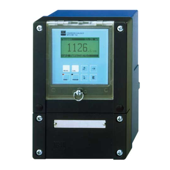
- Page 1 CLM 152 Conductivity Analyzer Operating Manual Quality made by Endress+Hauser The Power of Know How ISO 9001...
- Page 2 Please familiarize yourself with the instrument before you take any other steps: General Information Safety Description You want to install and start up the instrument. All the necessary steps can be found in these chapters: Installation First Start-up You want to operate or reconfigure the instrument. The operating concept is explained in these chapters: Operation Instrument Configuration...
-
Page 3: Table Of Contents
Section 4 Installation ..........................15 Storage and Transport ......................... 15 Unpacking ............................15 Mounting ............................... 15 Electrical Connection of Mycom CLM 152 ..................17 Connection of Conductivity Measuring Cells ..................30 Removal, Packaging and Disposal ....................32 Section 5 First Start-up ........................... 3 3 Measures Before the First Power-up .................... - Page 4 IMPORTANT NOTICE RETURN AUTHORIZATION POLICY Endress+Hauser must pre-approve and assign a Return Authorization number to any instrument you plan to return. Please identify the Return Authorization number clearly on all shipping cartons and paperwork. Please note that the issuance of a Return Authorization number does not automatically mean that credit will be issued, or that the return is covered by our warranty.
-
Page 5: Section 1 General Information
General Information 1.1 Symbols used Note! Caution! Warning! 1.2 Conformity Statement Note! - Page 6 (This page intentionally left blank)
-
Page 7: Section 2 Safety
Safety 2.1 Intended Application 2.2 General Safety Instructions Warning! 2.3 Safety Functions Access Code: Alarm Function: Data Integrity: Electromagnetic compatibility:... -
Page 8: Repairs, Hazardous Materials
2.4 Repairs, Hazardous Materials 2.5 Technical Improvements... -
Page 9: Section 3 Description
Description 3.1 Application Areas 3.2 Operating Principle General Principle Toroidal Conductivity 3.3 Measuring Functions Concentration Measurement Difference Measurement Polarization Compensation (Contacting) -
Page 10: Measuring System
Measuring Range Switching 3.4 Measuring System ¬ Figure 3.1 Example of a complete measuring system ¬ Mycom CLM 152 toroidal option Conductivity measuring cell (e.g. CLS 52) ¬ Figure 3.2 Example of a complete measuring system ¬... -
Page 11: Major Features
3.5 Major Features Note! -
Page 12: Instrument Versions
3.6 Instrument Versions CLM152- MYCOM CLM 152 Conductivity and resistance measurement transmitter Configuration and certificate 1-circuit; base version 1-circuit; feedback/hold contact/remote MR switching 2-circuit; base version 1-circuit; FM CL. I, Div 2; CL II/III Div 1; CL. I Zone 2; NI outputs 1-circuit;... -
Page 13: Accessories
3.7 Accessories 3.7.1 Supplied Accessories Endress+Hauser conductivity measuring cells that can be connected. Two-electrode measuring cells Toroidal measuring cells Figure 3.3 Conductivity measuring cells by Endress+Hauser Specified application range Extended measuring range due to polarization compensation... - Page 14 3.7.2 Calibration Solutions Type Conductivity Order at 77°F (25°C) Number 3.7.3 Junction Box VBM ² Figure 3.4 Dimensions of junction box VBM 3.7.4 Sensor Cable CLK 5 3.7.5 Sensor Cable CLK 71...
-
Page 15: Section 4 Installation
Installation 4.1 Storage and Transport 4.2 Unpacking 4.3 Mounting Figure 4.1 Dimensions for wall mounting... - Page 16 Mounting kit for panel installation and post mounting (order no. 50061357) ¬ Figure 4.3 ¬ Panel installation Post mounting of Mycom CLM 152 Mounting Accessories Figure 4.4 Weather protection cover 2.60 (66) 2.17 (55) Figure 4.5 1.18 Round post mounting kit...
-
Page 17: Electrical Connection Of Mycom Clm 152
4.4 Electrical Connection of Mycom CLM 152 Warning! Caution! Note! Instrument Connections Warning! - Page 18 4.4.1 Connection of Mycom CLM 152 in non-Ex (non-hazardous) Areas Figure 4.6 Connection compartment of Mycom CLM 152 (basic configuration) Conductivity input module FCL1 Motherboard (basic assembly) (slot 1) Temperature Conductivity Conductivity Temperature Failure Contact 1 Pwr Supply 88 AC:...
- Page 19 Note! Expansion Module FCL1 14 15 16 17 Figure 4.8 Connection of module FCL1 with toroidal Pt 100 sensor 14 15 16 17 Figure 4.9 Connection of module FCL1 with contacting Pt 100 sensor Expansion Module FCYK: Contact 2 Contact 3 Contact 4 Figure 4.10 Connection of module...
- Page 20 Connection for Use of Internal Auxiliary Voltage Power supply Contact inputs Figure 4.12 Connection of module FCXI as an integral power supply Technical Data Expansion Module FCYP Profibus Figure 4.13 Connection of module FCYP...
- Page 21 4.4.2 Connection of Mycom CPM 152-F and CLM 152-F in Ex (Hazardous) Areas with NI Outputs (Page 1 of 3)
- Page 22 Connection of Mycom CPM 152-F and CLM 152-F in Ex (Hazardous) Areas with NI Outputs (Page 2 of 3)
- Page 23 Connection of Mycom CPM 152-F and CLM 152-F in Ex (Hazardous) Areas with NI Outputs (Page 3 of 3)
- Page 24 4.4.3 Connection of Mycom CPM 152-G and CLM 152-G in Ex (Hazardous) Areas with IS Outputs (Page 1 of 3)
- Page 25 4.4.3 Connection of Mycom CPM 152-G and CLM 152-G in Ex (Hazardous) Areas with IS Outputs (Page 2 of 3)
- Page 26 4.4.3 Connection of Mycom CPM 152-G and CLM 152-G in Ex (Hazardous) Areas with IS Outputs (Page 3 of 3)
- Page 27 Connection Compartment and Connection Diagram Figure 4.14 Connection compartment of Mycom CLM 152 (Ex) Conductivity input module (Ex) Current output module (Ex) Motherboard (basic assembly) (FCL1 / slot 1) (FCYI / slot 2) Temperature Conductivity Conductivity Temperature Failure Contact 1 Pwr Supply PE (AC) 15 16 17...
- Page 28 Note! Expansion Module FCL1 (toroidal): 14 15 16 17 Figure 4.16 Connection of module Pt 100 FCL1 Expansion Module FCYK-Ex: Contact 2 Contact 3 Contact 4 Figure 4.17 Connection of module FCYK, Ex Expansion Module FCXI: Contact outputs Current input Figure 4.18 Connection of module FCXI...
- Page 29 Analog/Contact Input Module Switch 1 Intrinsically safe ia/ib circuit 1: Ci,max = 15nF Voltage supply = 4 to 30 V Li,max = 53 µH Current consumption @ 30 V, max. 100 mA Switch 2 Intrinsically safe ia/ib circuit 2: Ci,max = 15nF Voltage supply = 4 to 30 V Li,max = 53 µH...
-
Page 30: Connection Of Conductivity Measuring Cells
4.5 Connection of Conductivity Measuring Cells Caution! Note! Toroidal Measuring Cell Blue White Coax inside 17 Coax shield 16 Coax shield 15 Blue Coax inside 14 White Brown Green/Yellow Green Figure 4.21 Sensor CLS 52 with connecting cable White Coax inside 17 Blue Coax shield 16 Blue... - Page 31 Contacting Measuring Cell Figure 4.23 Sensor CLS 15/CLS 21 with connection cable...
-
Page 32: Removal, Packaging And Disposal
Construction and Preparation of Cable CYK71 and CYK5 ³ ® ² ° ¯ ¬ ¬ ® Caution! ¯ ° ± ² ³ ¯ ¬ ± ² ³ Figure 4.24 Construction / preparation of special measuring cable CYK5 4.6 Packaging and Disposal Packaging Disposal... -
Page 33: Section 5 First Start
First Start-up 5.1 Measures Before the First Power-up Caution! Warning! 5.2 The “Set-up Guide” Menu... - Page 34 Set-up Guide / Checklist Prompt Possible Choices Factory Settings User Settings...
-
Page 35: Section 6 Operation
LED with no function Figure 6.1 4 keys for calling up Operating elements the main groups Mycom CLM 152 Toroidal 6.2 Display Main measured value (in measuring mode) or Operating mode or Present current value current measured parameters (e.g. in calibration, configuration) -
Page 36: Key Functions
6.3 Key Functions Measurement Calibration Diagnostics Parameter Configuration Enter 6.4 Operating Concept ¯ Note! ® ¯... - Page 37 Note! Figure 6.3 Diagram of the Mycom operating concept Hold Function...
-
Page 38: Measured Value Displays
6.5 Measured Value Displays ¯ Note! Conductivity Measurement Concentration Measurement... -
Page 39: Locking Of Functions
Resistance Measurement 6.6 Locking of Functions Note! Figure 6.4 Code prompt... -
Page 40: The “Shortcut To Relays” Menu
Accessible Without Code Entry: Accessible With Operator Code: Accessible With Advanced Code: Caution! 7156 6.7 The “Short-Cut to Relays” Menu ® Short-Cut to Relays Menu... -
Page 41: Section 7 Instrument Configuration
Instrument Configuration Note! ® Set-up guide ® Short-cut to relays ® Commissioning (Start-up) ® ® ® ® ® ®... -
Page 42: System Configuration
7.1 System Configuration ® ® ® ® ® ® 7.1.1 Measurement Type Caution! Note! - Page 43 7.1.2 Measuring Range Switching Remote Measuring Range Switching Measuring Range MR 1 MR 2 MR 3 MR 4 Automatic Measuring Range Switching with Conductivity-Mode Example (mS/cm) MR 4 20000 18000 MR 3 2000 1800 MR 2 MR 1 Contact state Contact 3 Figure 7.1 Contact 4...
- Page 44 7.1.3 Code 7.1.4 Output Relays Caution! Toroidal Contacting Contact assignments for base version...
- Page 45 N " , " N " / " o i t c t i u l i u l i u l i u l i u l i u l i u l i o i t o i t o i t Note! “failure contact”...
-
Page 46: Current Output
7.1.5 General 7.2 Current Output ® ® ® ® ® 7.2.1 Current Output Current output signal: characteristics and assignment... - Page 47 A) Linear Current Output Signal Characteristic Figure 7.2 Current output signal with linear characteristic...
- Page 48 Example: Measuring Range Assignment of a Measuring Cell with CLS 52, Rising Characteristic Bilinear Current Output Signal Characteristic Figure 7.3 Current output signal with bilinear characteristic Logarithmic Current Output Signal Characteristic Figure 7.4 Current output signal with logarithmic characteristic...
- Page 49 User-Selectable Current Output Characteristic Figure 7.5 Example of a characteristic with 2 and 4 value pairs 1: Actual curve 2: Interpolated curve...
- Page 50 Programming 7.2.2 Hold Type (Current Output During Hold) Note!
-
Page 51: Temperature Compensation
7.3 Temperature Compensation ® ® ® ® Figure 7.6 Concentration dependence of temperature coefficient for various electrolyte solutions (reference temperature T = 77°F/ Concentration (percent by weight) 25°C) Figure 7.7 Dependence of temperature coefficient on temperature for NaCI Temperature °F (°C) solutions. - Page 52 7.3.1 Temperature Compensation first four ¯ ® ® ¯ ¯...
- Page 53 7.3.2 Temperature Measurement Manual Temperature Compensation (MTC): Automatic Temperature Compensation (ATC):...
-
Page 54: Calibration Settings
7.4 Calibration Settings ® ® 7.5 Cleaning Function ® ® Note! -
Page 55: Substance Selection / Concentration Measurement
7.6 Substance Selection / Concentration Measurement ® ® Note! - Page 56 (This page intentionally left blank)
-
Page 57: Instruments With Two Contacts
Limit Configuration Limit Monitor Example for two limit contacts MIN function MAX function 100 % Figure 8.1 Control characteristic of a limit contacter = system deviation – X Limit 1 Limit 2 = manipulated variable output 8.1 Instruments with Two Contacts ®... -
Page 58: Instruments With Five Contacts
8.2 Instruments with Five Contacts ® ® Note! -
Page 59: Usp Function (Contacting Mode)
8.3 USP Function (Contacting mode) USP Requirements on Measurement The USP function can be activated in the Commissioning / System set-up / Output relays menu. ® ®... - Page 60 (This page intentionally left blank)
-
Page 61: Section 9 Calibration
Calibration 9.1 Toroidal Calibration ® ® ® ® 9.1.1 Entry of Code 9.1.2 Input of Cell Constant 9.1.3 Evaluation of Cell Constant Þ Þ Þ... - Page 62 Note! Note! 9.1.4 Installation Factor (with Toroidal Sensors) Input of Installation Factor...
-
Page 63: Contacting Calibration
Note! Evaluation of Installation Factor 9.2 Contacting Calibration ® ® 9.2.1 Numerical Calibration / Input of Cell Constant Cell Constant Entry range... - Page 64 9.2.2 Wet Calibration / Determination of Cell Constant “E” Display: measured value of calibration solution, ATC/MTC, temperature, Tc of calibration solution. “E” Enter the setpoint. The computed cell constant is displayed. Note! Warning!
-
Page 65: Section 10 Profibus Interface
10 Profibus Interface 10.1 FCYP Module PC with operating program Commuwin II PROFIBUS DP Pipelines with conductivity sensors Segment coupler Figure 10.1 Measuring system based on Mycom CLM Field bus with 152 with PROFIBUS PA PROFIBUS PA protocol 10.2 Bus Cable Caution! -
Page 66: Bus Address
10.3 Bus Address Ü Ü Ü Ü Figure 10.2 Section of Profibus card in Mycom showing address setting 126 (factory setting for software addressing) Addressing Examples... -
Page 67: Device Master File / Type File
10.4 Device Master File / Type File 10.5 Remote-Controlled Operation with Commuwin II Figure 10.3 Instrument data (commissioning) menu displayed in Commuwin II (contacting) Establishing the Connection Figure 10.4 Operation via graphical user interface of Commuwin II... -
Page 68: System Integration Via Plc
10.6 System Integration via PLC Data Format for Module 1 and Module 2 IEEE 754 Floating Point Number... -
Page 69: Profibus Pa Parameters
10.7 Profibus PA Parameters 10.7.1 Profibus PA Parameters for Toroidal Measurement Parameter Matrix Index Data Type Read Write Data (Slot = 1) - Page 70 10.7.2 Profibus PA Parameters for Contacting Measurement Parameter Matrix Index Data Type Read Write Data (Slot = 1)
-
Page 71: Section 11 Diagnostics
Diagnostics 11.1 Error Messages 11.1.1 Error Classification Category Error Number Effect 11.1.2 Error List and Error Logbook Error List ¯ Error Logbook ¯ ... - Page 72 11.1.3 Error Table Failure Maintenance Required...
- Page 73 Disturbances Warnings...
-
Page 74: Instrument Information
11.2 Instrument Information 11.2.1 Information List 11.2.2 Logbook 11.3 Air Set Information (Toroidal) 11.4 Calibration History Caution! -
Page 75: Service
11.5 Service ® ® ® ® ® ® 11.5.1 Simulation ¯ ® Note! 11.5.2 Internal Data... - Page 76 11.5.3 Factory Settings Þ Caution! All previous instrument configuration data is lost! Caution! All previous calibration data is lost! Caution! All previous configuration and calibration data is lost! Caution! 11.5.4 Instrument Check...
- Page 77 11.5.5 Special Functions Warning!
- Page 78 (This page intentionally left blank)
-
Page 79: Section 12 Maintenance And Service
Maintenance and Service 12.1 Cleaning Warning! 12.2 Fuse Replacement Figure 12.1 Fuse holder of non-Ex version Non-Ex Version: Ex-Version: 12.3 Repairs... - Page 80 (This page intentionally left blank)
-
Page 81: Section 13 Appendix
Appendix 13.1 Technical Data (Toroidal) 13.1.1 Technical Data with CLS 50 General Specifications Continuous Operating Temperature A B5 Pressure Resistance Temperature Measurement Measuring Cell Material PFA Version with G 3/4 Connection and ANSI 2” (DN 50) Flange PEEK Version Installation... - Page 82 13.1.2 Technical Data with CLS 52 General Specifications Conductivity Measurement Concentration Measurement Temperature Compensation Temperature Measurement Specifications for sensor CLS 52...
- Page 83 13.1.3 Technical Data with Contacting Electrodes Conductivity/Resistance/ Concentration Measurement l l e µ µ µ µ µ µ µ µ µ l l e Ω Ω m Ω Ω m Ω Ω m Ω Ω m Ω m Ω m µ...
- Page 84 13.1.3 Technical Data with Contacting Electrodes (continued) Temperature Measurement Limit and Alarm Functions Electrical Data and Connections...
- Page 85 13.1.3 Technical Data with Contacting Electrodes (continued) General Technical Data Physical Data...
- Page 86 13.1.4 General Technical Data Limit and Alarm Functions Electrical Data and Connections General Technical Data Physical Data...
-
Page 87: Profibus Pa
13.2 Profibus PA Output Specifications Display and User Interface Power Supply... -
Page 88: Connection Examples (Toroidal)
13.3 Connection Examples (Toroidal) 13.3.1 Lye-Acid Recycling with Concentration Measurement Failure Maint. requirement Function check Limit 1... - Page 89 13.3.2 Difference Measurement for Juice Production Failure Maint. requirement Function check...
-
Page 90: Connection Examples (Contacting)
13.4 Connection Examples (Contacting) 13.4.1 Limit Contacter, NAMUR Contacts Failure Maint. requirement Function check Limit 1... - Page 91 13.4.2 Chemoclean, NAMUR Contacts Failure Maint. requirement Function check Water Cleaner...
- Page 92 13.4.3 Difference Measurement, Limit Contacter, NAMUR Contacts Failure Maint. requirement Function check Limit1 Limit 2...
-
Page 93: Section 14 Index
Index... - Page 96 Parameter Meas. type Measuring cell Meas. principle Unit Temperature sensor 1 Instrument data System Conductivity CLS 50, CLS 52, 1-circuit PT 100 configuration Concentration 2-ring: k = 0,01; Difference PT 1000 PARAM Resistance k = 0,1; k = 1; k = 10 (only difference) NTC 30 kW Code...
- Page 97 T emperature sensor 2 Input contacts PT 100 PT 1000 (only for (only with FCXI) NTC 30 k d ifference) tag number Profibus address Contrast (only FCYP) Remote meas. range Meas. current Meas. current range switch-over (linear) ranges 1-4 at 20 mA Meas.
- Page 100 Parameter Measuring type Measuring cell Measuring principle Unit Temperature sensor 1 Instrument data System Conductivity CLS 50, CLS 52, 1-circuit PT 100 configuration Concentration 2-ring: k = 0,01; Difference PT 1000 PARAM Resistance k = 0,1; k = 1; k = 10 (only difference) NTC 30 kW Repair code...
- Page 101 T emperature sensor 2 Input contact PT 100 PT 1000 (only for (only with FCXI) NTC 30 k difference) tag number Profibus address Contrast (only FCYP) Remote meas. range Meas. current Meas. current range switch-over (linear) ranges 1-4 at 20 mA Meas.
- Page 102 Phone: (905) 681-9292 FAX: (780) 486-3466 1-800-668-3199 FAX: (905) 681-9444 Regional Office Sterling IPC Endress+Hauser Endress+Hauser Div. of Endress+Hauser Canada Ltée P.O. Box 901 68950 Powell Road 6800 Côte de Liesse, Ste. 100 Harvey, LA 70059 P.O. Box 604 St. Laurent, Québec...
Need help?
Do you have a question about the mycom CLM 152 and is the answer not in the manual?
Questions and answers