Table of Contents
Advertisement
Quick Links
Advertisement
Table of Contents

Subscribe to Our Youtube Channel
Related Manuals for Houghton BELAIRE H2400D


Summary of Contents for Houghton BELAIRE H2400D
- Page 2 Safety Notices Dear user, thank you for choosing a HOUGHTON caravan air-conditioner. For your ease of use and safe maintenance we have included the following symbols in this manual: All the contents with this “Warning” logo are about the safety of the product and the user, the user shall operate in strict compliance with the instructions.
-
Page 3: Table Of Contents
Table of Contents Safety Notes..............................4 Product Introduction............................5 Packing List..............................6 Installation Guidance...........................7 Instructions for Use........................... 10 Operation Instruction..........................11 Product Maintenance..........................18 Specification Parameters........................... 19 Exploded Diagram and Parts List......................20 Trouble shooting guide..........................21 Circuit Diagram............................22 Unit Floor Template..........................23... -
Page 4: Safety Notes
Safety Notes Make sure the external electric supply socket of the caravan air-conditioner is effectively grounded in accordance with your local regulations. Failure to ground the unit correctly may cause electric shock or fire. The caravan air-conditioner shall be switched on for electric leakage detection after installation. -
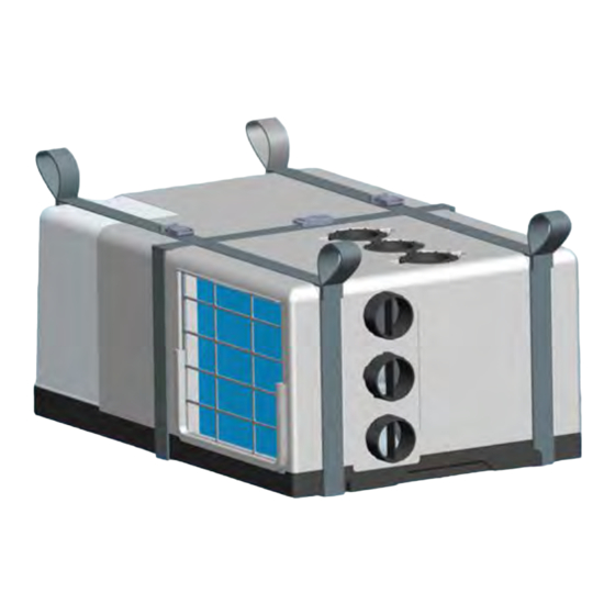
Page 5: Product Introduction
Many factors will affect the total heat load within the caravan and many factors can also affect the working efficiency of the air-conditioner. Before purchasing HOUGHTON BELAIRE, the user shall consult with the caravan manufacturer to understand the total heat load of the caravan and to choose the correct air-conditioner for the application. -
Page 6: Packing List
Failure to properly install the unit or attempting to modify it in any way can be extremely hazardous and may result in property damage and/or personal injury. HOUGHTON will not be held responsible for issues arising from incorrect or improper installation methods. -
Page 7: Installation Guidance
in an appropriate location, the cable length from the unit to the touch screen is 4m. (Extension cables are available, contact HOUGHTON if needed). The filter side of the unit should face the open side of the Figure 3-Minimum spacing for a fully enclosed unit with... - Page 8 Cut out the required hole and secure the grille in place Contact HOUGHTON if your installation differs significantly using the supplied screws. from that prescribed above. If you are not using the supplied return air grille then the ...
- Page 9 If the supply cord is damaged, it must be replaced onto the backing plate .(Figure 9) by HOUGHTON, one of its service agents or similarly qualified persons in order to avoid a hazard. With a flat head screw driver or similar pop off the rear ...
-
Page 10: Instructions For Use
Instructions for Use 1.Turn the power on at the circuit breaker. 2.Press the ON/OFF “ ” button and set the time and day (see operating instructions). Then press the MODE button “ ” to select FAN “ ”. 3.Cycle through the LOW, MED and HIGH fan speeds checking that all speeds run. 4.Set mode to COOL, adjust temperature via up/down buttons to 4˚C below the display temp (i.e. -
Page 11: Operation Instruction
Operation Instruction Remote controller... - Page 12 1. Operation of the remote controller Turn on Press the on/off “ ” key, the machine turns on, the buzzer of the LCD touchscreen beeps one time and the running mode and temperature will be displayed. FAN mode Press the “MODE” key, select the mode, Press the “FAN”...
- Page 13 DRY mode Press the “MODE” key, select the “ ” mode, Press the down “▼” key to set the temperature 1℃ lower than the room temperature , and the LCD touchscreen will display “ ” and the temperature. HEAT mode Press the “MODE”...
- Page 14 Note When in the AUTO mode, according to the difference between the setting temperature and the environmental temperature , the LCD touchscreen will display “ ”and “ ”(automatic heating), or “ ” and “ ” (automatic cooling) in the same time. Celsius and Fahrenheit degree change In any mode,Press the“℃/℉”key,you can select temperature between Celsius and Fahrenheit.
- Page 15 LCD touchscreen control panel 2. LCD touchscreen operation DAY/TIME setting Press “ ” and “ ” for 3 seconds to enter day/time setting menu. Display will show “ ” blinking for 6 seconds. Press “ ” to change the day setting. ...
- Page 16 FAN mode For simply recirculating air, choose the Fan mode “ ”. Choose any of the three fan speeds by pressing the fan button “ ”. Note: Temperature button is invalid in Fan only mode. HEAT mode Cycle mode button to highlight the sun icon “ ”.
- Page 17 TIMER (will work only when set on the LCD touchscreen, it will NOT work if set by the remote) The timer function may be used to turn the unit either off or on at any point during the week. Note: ensure that you have correctly set the time and day before attempting to set the timer.
-
Page 18: Product Maintenance
If you have a claim please contact HOUGHTON, please have your unit serial number ready (which can be found on the sticker on top of the unit). -
Page 19: Specification Parameters
Specification Parameters H2400D Model 230-240VAC/50Hz Power supply R407C/500g Refrigerant charged 2400 Rated cooling capacity (W) 2000 Rated heating capacity (W) Input power for cooling (W) Input power for heating (W) Rated current for cooling(A) Rated current for heating(A) 1120 Maximum input power(W) Maximum current(A) 2900 Maximum design pressure (... -
Page 20: Exploded Diagram And Parts List
Exploded Diagram and Parts List Figure No. Name Note Filter 4738-1000-10 Unit (without ducting) 4738-1000-00 4738-0000-17 Ducting outlets Inside fan assembly 4738-1010-00 Thermostat switch 4640-2020-02 Electronic control board 4708-1241-01(f) Top foam canopy 4738-1000-03 Buckles and straps (all 3 included) 4738-1000-17/18 Power cord 4658-1700-03 Return air grille... -
Page 21: Trouble Shooting Guide
Trouble shooting guide No display of the LCD touchscreen E1: Room temperature sensor Check whether the access to the power of the RV OK? Fault in connection to temperature sensor or Poor connecting of the control line between the other damage. -
Page 22: Circuit Diagram
Circuit Diagram... -
Page 23: Unit Floor Template
Unit Floor Template... - Page 24 V0 4738-2000-01...
Need help?
Do you have a question about the BELAIRE H2400D and is the answer not in the manual?
Questions and answers