
Subscribe to Our Youtube Channel
Related Manuals for Houghton BELAIRE H3400


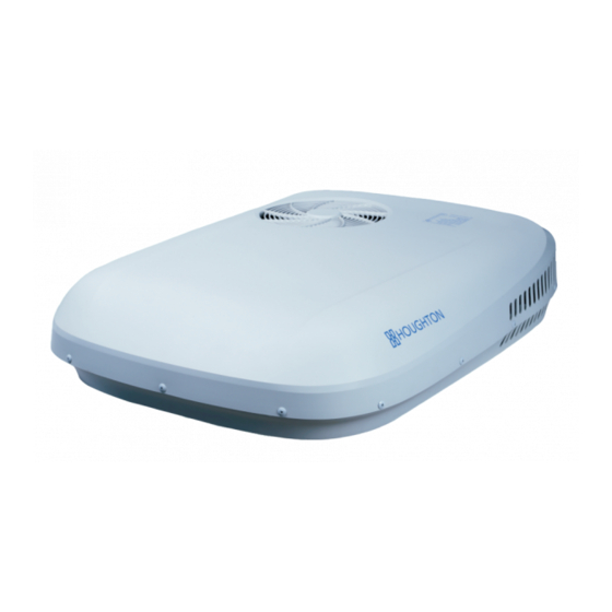
Summary of Contents for Houghton BELAIRE H3400
- Page 1 ODEL UMBER: ERIAL UMBER: URCHASED: OWNERS MANUAL CARAVAN AIR-CONDITIONER MODEL H3400 A3400 A3401 For your safety,please read this manual carefully before using the product.
- Page 2 Safety Notices Dear user, thank you for choosing a HOUGHTON caravan air-conditioner. For your ease of use and safe maintenance we have included the following symbols in this manual: All the contents with this "Warning" logo are about the safety of the user and the air-conditioner.
-
Page 3: Table Of Contents
Table of Contents Safety Notes..............................1 Product Introduction............................ 2 Packing List..............................3 Installation Guidance........................... 4 Quick Start Guide ........................... 10 Remote control operation.......................... 11 Product Maintenance..........................18 Specifications............................19 Exploded Diagram and Parts List......................20 Trouble Shooting Guide..........................23 Circuit Diagram............................24... -
Page 4: Safety Notes
Safety Notes Make sure the external electric supply socket of the caravan air-conditioner is effectively grounded in accordance with your local regulations. Failure to ground the unit correctly may cause electric shock or fire. The caravan air-conditioner shall be switched on for electric leakage detection after installation. -
Page 5: Product Introduction
Product Introduction Purpose HOUGHTON BELAIRE is designed to provide a comfortable environment inside a recreational vehicle or caravan Achieving effective heating & cooling Many factors will affect the total heat load within the caravan and many factors can also affect the working... -
Page 6: Packing List
11.Countersunk head self tapping screws ST4.2×16 × 10 12.Truss head tapping screws ST4×10 ×4 Not shown: Manual ×1 ● Remote control & bracket ×1 ● If you note that any items are missing or damaged then please contact Houghton or the local distributor. -
Page 7: Installation Guidance
The installers shall be equipped with refrigeration technician qualification certificates and/or suitable electrical trade qualifications. ● Consult with HOUGHTON or the local distributor in the case of unusual applications or installation conditions that are not specifically covered by this manual. Installation requirements The RV or caravan roof shall be able to support the air-conditioner ’s weight (45kg /99 lbs). - Page 8 Angle of inclination of the air-conditioner shall not be greater than 5° and the rear of the air-conditioner shall not be higher than the front. For advice on installations outside of these limits please contact HOUGHTON or the local distributor. The figure below shows the minimum clearance distance required between the BELAIRE air-conditioner and any ●...
- Page 9 13 15/16" Unit: inch 6 7/8" Plenum position 14 3/16" Direction of travel 33 1/2" 20 5/16" 14 3/16" Square hole (14 ") × 14 22 5/8" Position of rooftop unit 44 3/16" Installation of roof mount Make sure the roof is clean, dry and free from oil or grease. ●...
- Page 10 Note Connect the wall-mounted switch The outdoor unit weighs about 45kg / 99 lbs (Applies to Units with LED lighting) use appropriate manual handling precautions. Locate the pair of blue wires labelled " Wall Switch " ● Use the M8 bolts and check if the holes are These wires can be connected to a NC or NO switch aligned with the holes of the plenum mounting to allow for control of LED lighting via a familiar...
- Page 11 Connect the socket and plug of the display panel. ● Please note that colors of the wires should be match. (yellow to yellow, red to red etc) Connection of air inlet duct Grasp the free end of the air inlet duct and pull it ●...
- Page 12 The installation is completed This next section is not compulsory - if required Adjust the louver to pull the plenum up to the ceiling and remove any gaps. Adjust direction and angle of louver by moving ● Remove the screw caps from around the perimeter of blade around its axis The 2 blades move together ●...
-
Page 13: Quick Start Guide
Quick Start Guide Switch on the power to the air-conditioner at the isolation breaker. ● Using the remote control , start the air-conditioner by pressing " " button and then select fan ● function by pressing the "MODE" button. Operate in low FAN, medium FAN and high FAN in turn to check normal operation. ●... -
Page 14: Remote Control Operation
Remote control operation Standard remote control... - Page 15 Remote control for units with LED lighting Plenum display Touch screen key Temperature Mode display display...
- Page 16 1. Operation of the remote control Turn on Press the on/off key, the unit turns on, the plenum buzzer beeps once and the running mode and temperature will ● " " be displayed. FAN mode " " " " " "...
- Page 17 DRY mode mode, Press the down ▼ " " " " " " Press the key, select the key to set the temperature 1℃ lower than the ● MODE room temperature , and the plenum will display " " and the setting temperature. MODE HEAT mode ▲...
- Page 18 Note When in the AUTO mode, according to the difference between the setting temperature and the environmental temperature , the plenum will display " " (automatic heating), or " " " " (automatic cooling) in the same time. " " Celsius and Fahrenheit degree change "...
- Page 19 LED lighting function Press the " LIGHT " key, the plenum LED lighting will turn on. ● When LED lighting is on, press the " DIM " key to select 25% / 50% / 75% / 100% brightness. The plenum LED ●...
- Page 20 2. Plenum operation Basic air-condition features can be accessed via the plenum control This is useful if the remote control has been lost or is not functioning . The selected mode will cycle through " OFF " " ● Press the touch screen key on the plenum ->...
-
Page 21: Product Maintenance
Product Maintenance Filter ● The return air filter is the only component that needs periodic maintenance ● Check and clean the filter each week when in use to prevent the filter from being blocked by dirt The filter should be washed frequently to ensure effective cooling and heating ●... -
Page 22: Specifications
Specifications Model H3400 A3400 A3401 Power supply 115V/60Hz 115V/60Hz 220~240V/50Hz Refrigerant charged R407C/ 900g R410A/ 910g R410A/ 910g Rated cooling capacity 3400W 13500BTU/H 13500BTU/H Rated heating capacity 3000W 12000BTU/H —— Input power for cooling (W) 1350 1550 1550 —— Input power for heating (W) 1250 1550 Rated current for cooling (A) -
Page 23: Exploded Diagram And Parts List
Exploded Diagram and Parts List... - Page 24 Figure No. Name 18-12-13 Mushroom head screw, white, M5 4708-1000-01(ZH4) Canopy (silk-screened) 1(H3400 ) Canopy (silk-screened) 7398-1000-01 1(A3400/A3401) 4708-1000-08 (ZL) Evaporator housing 4708-1701-06 Electrical box lid Compressor run capacitor (30 μF) TDQ-04204 1(H3400 ) 7280-1700-03 (ZH2) Compressor run capacitor (60 μF) 1(A3400/A3401) 4708-1701-07 Electrical box 2...
- Page 25 Figure No. Name 4709-1100-01 Metal clamping bar M8 hex head bolt (M8 120) 18-10-59 × Plenum mounting bracket 4709-0000-02 4709-1000-01(ZH2) Plenum assembly 1(H3400 with LED lighting) 4709-1000-01(DM) Plenum assembly 1(H3400 without LED lighting) 4709-1000-01 Plenum assembly 1(A3400/A3401) 4708-1241-01(d) Display board 4709-1000-04 Air filter 7339-1700-02(GG)
-
Page 26: Trouble Shooting Guide
Can you hear the compressor starting or stopping in heating or cooling mode Poor cooling capacity Your help in collecting this information will greatly assist the Houghton service team in To make sure the filter is clean ● correcting any problems Thank you. -
Page 27: Circuit Diagram
Circuit Diagram 220-240VAC 50Hz H3400 WIRING DIAGRAM (without LED lighting) H3400 WIRING DIAGRAM (with LED lighting) - Page 28 115VAC 60Hz A3400/A3401 WIRING DIAGRAM...
- Page 29 V5 4708-2000-01(ZH3)
Need help?
Do you have a question about the BELAIRE H3400 and is the answer not in the manual?
Questions and answers
Does the Belair 3400 have a circuit breaker?