Advertisement
Available languages
Available languages
Quick Links
FR
GB
DE
IT
ES
Find Quality Products Online at:
- Notice de fonctionnement p. 1
- Operating instructions p. 16
- Bedienungsanleitung S. 31
-
p. 46
- Manual de instrucciones p. 61
Pince pour oscilloscope
Clamp for oscilloscope
Zangenstromwandler für Oszilloskop
Pinza per oscilloscopio
Pinza para osciloscopio
GlobalTestSupply
www.
MH 60
.com
sales@GlobalTestSupply.com
Advertisement
Chapters

Related Manuals for Chauvin Arnoux MH 60


Summary of Contents for Chauvin Arnoux MH 60
- Page 1 - Notice de fonctionnement p. 1 - Operating instructions p. 16 - Bedienungsanleitung S. 31 p. 46 - Manual de instrucciones p. 61 MH 60 Pince pour oscilloscope Clamp for oscilloscope Zangenstromwandler für Oszilloskop Pinza per oscilloscopio Pinza para osciloscopio GlobalTestSupply www.
- Page 2 GlobalTestSupply www. .com Find Quality Products Online at: sales@GlobalTestSupply.com...
-
Page 3: Table Of Contents
Pince pour oscilloscope SOMMAIRE 1. INTRODUCTION ..........................3 1.1. Présentation ..........................3 1.2. Sécurité ............................3 2. DESCRIPTION ..........................4 3. FONCTIONS DES TOUCHES ET DES LEDs.................. 4 3.1. Fonctions de la Touche ON/OFF....................5 3.1.1. Démarrer........................... 5 3.1.2. Arrêter............................5 .................. -
Page 4: Introduction
1. INTRODUCTION 1.1. Présentation La pince MH 60 est une sonde de courant pour oscilloscope utilisant une cellule à effet Hall, permettant la mesure de courant continu ou alternatif jusqu'à 100A eff sans intervention sur l'installation électrique (coupure du courant à mesurer). C'est un transducteur à... -
Page 5: Description
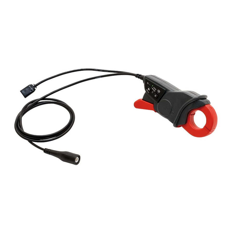
Pince pour oscilloscope 2. DESCRIPTION 1. Mâchoires 2. Passage du conducteur 3. Garde anti-glissement de protection 4. Clavier (voir ci-dessous) 5. Gâchette ouverture 6. Cordons solidaires : BNC 2m et USB 0,3m 3. FONCTIONS DES TOUCHES ET DES LED Ce clavier est le repère 4 de la figure ci-dessus : Filtre 3 kHz (verte) Symbole Auto Off Filtre 30 kHz (verte) -
Page 6: Fonctions De La Touche On/Off
Dans le cas où rompt suite à un accumulateur trop déchargé, mémorisé, puis restitué, rétablie. suivant : la pince MH 60 est sur « ON ». Maintenir la touche enfoncée et appuyer sur La main Relâcher les touches... -
Page 7: Effectuer Le Dc-Zéro
, la LED , elle reste allumée. Le statut ERR est généralement provoqué par l courant dans un conducteur clampé. La pince MH 60 incorpore nfluence des champs extérieurs, notamment le champ terrestre. Exemple : Je fais le zéro, plan des mâchoires : pour «... -
Page 8: Alimentation
Pince pour oscilloscope 3.4.2. Fonctionnement avec alimentation USB La pince est « OFF ». Brancher USB. charge clignotement toutes les secondes ; en fin de charge, cette LED reste allumée. La pince est « ON ». Brancher permanente la LED est allumée en permanence. -
Page 9: Mode Operatoire
Pince pour oscilloscope 5.1. Mise en Respecter la tension de 300 V (CATIII) ou 600 V CATII) par rapport à la terre, d'un conducteur non isolé. Utiliser la pince sur des conducteurs dont le courant est inférieur ou égal à la valeur maximale autorisée en régime permanent, soit 100 A eff ou 140 A crête. -
Page 10: Caracteristiques Techniques
Pince pour oscilloscope 6.1. Conditions de référence Grandeur d'influence Conditions de référence Mise en marche avant mesure 1 mn Température ambiante 23°C ± 5 K Humidité 20% Hr à 75% Hr Fréquence du DC à 400 Hz Position du conducteur centré... -
Page 11: Conditions D'environnement
Pince pour oscilloscope 6.3. Domaine nominal d'utilisation 6.3.1. Conditions d'environnement 1 = Domaine de référence 2 = Domaine de fonctionnement 3 = Domaine de stockage Le domaine de stockage est réd n accumulateur. A la décharge Il faut donc pré-charger complètement à... -
Page 12: Compatibilité Et Susceptibilité Électromagnétiques
Pince pour oscilloscope 6.3.2. Compatibilité et susceptibilité électromagnétiques 6.3.3. Protection contre les chocs électriques Pince de type A à isolation double ou isolation renforcée dans la partie préhensible en utilisation normale, et isolation double ou isolation renforcée entre le primaire et la sortie secondaire sortie BNC. -
Page 13: Conditions Limites
Pince pour oscilloscope 6.4. Conditions limites - Surcharge : 1500 A pendant 1 min. 6.5. Limites en fréquence suivant le courant de mesure En utilisation normale 100 A 45 kHz. Derating en fréquence au-delà de 100 A 45 kHz : Suivant la formule : 100 A x (F en kHz) GlobalTestSupply... -
Page 14: Caracteristiques Mecaniques
Pince pour oscilloscope 7. CARACTERISTIQUES MECANIQUES Type Partie concernée Caractéristiques Nota dimensions 138 x 49 x 28 mm hors tout Pince masse 200 g env. avec câble et accu boîtier V2 (UL94) autoextinguibilité mâchoires V0 (UL94) câbles V0 (UL94) BNC et USB ouverture maximale 27 mm couleur rouge... - Page 15 Pince pour oscilloscope 7.1. (réf. P01296049). Déconnecter le chargeur USB et dé-clamper la pince de tout circuit. Retirer les deux vis de fermeture du boîtier. Identifier le connecteur Accu deux points et le débrancher. -clipser. Remontage GlobalTestSupply www. .com Find Quality Products Online at: sales@GlobalTestSupply.com...
-
Page 16: Procédure
Pince pour oscilloscope Mise en garde : cet ajustage que si le coefficient de gain est manifestement hors tolérance. Vérifier au préalable que les mâchoires ne sont pas pince est suffisamment chargée. Débrancher le chargeur USB. Contrôle du gain : Matériel nécessaire : Calibrateur de courant AC à... - Page 17 GlobalTestSupply www. .com Find Quality Products Online at: sales@GlobalTestSupply.com...
- Page 18 6.4. Extreme conditions........................27 6.5. Frequency limits depending on the measurement current ............ 27 7. MECHANICAL CHARACTERISTICS .................... 28 7.1. Replacing the storage battery ....................29 7.2. Gain adjustment procedure for the MH 60 ................30 GlobalTestSupply www. .com Find Quality Products Online at:...
-
Page 19: Introduction
Oscilloscope clamp 1. INTRODUCTION 1.1. Presentation The clamp is an oscilloscope current probe using a Hall effect cell, allowing the measurement of direct or alternating currents up to 100Arms without intervention on the electrical installation (cutting off of the current to be measured). It is a transducer delivering a voltage output. -
Page 20: Description
Oscilloscope clamp 2. DESCRIPTION 1. Jaws 2. Passage of the conductor 3. Non-slip guard 4. Keypad (see below) 5. Opening trigger 6. Integrated leads: 2m BNC and 0.3m USB 3. FUNCTIONS OF THE KEYS AND OF THE LEDS This keypad is item 4 in the figure above: 3kHz filter (green) Auto Off symbol 30kHz filter (green) -
Page 21: Functions Of The On/Off Key
Oscilloscope clamp 3.1. Functions of the 3.1.1. Switching on Long-press the key. The clamp MH60 acknowledges with the LED. Then release . The "ON" state of the MH60 clamp is indicated by the sequential lighting of the "BAT" LED. 3.1.2. Switching off Long-press the key (2s). -
Page 22: Adjust The Dc-Zero
Oscilloscope clamp 3.2.2. Adjust the DC-Zero The clamp must not be on a conductor, the jaws must be closed. Long-press the key (approx. 2s). The DC-Zero function is then activated. During the process, the LED is lit. At the end of the process, if there is no ERR, the LED goes off. -
Page 23: Operation With The Usb Supply
Life: 2 years minimum Nr. of recharging cycles: This type of storage battery can be procured from CHAUVIN ARNOUX. Power supply: from the Type B µUSB connector. Max. consumption (with storage battery charging): <170mA 4.1. Recharging of the internal storage battery The internal storage battery can be recharged in the presence of an external power source, with the clamp off. -
Page 24: Operating
Oscilloscope clamp 5.1. Precautions Do not exceed the voltage of 300V (CAT III) or 600V (CAT II) with respect to earth with an uninsulated conductor. Use the clamp on conductors in which the current is less than or equal to the maximum continuous value allowed, namely 100Arms or 140A peak. -
Page 25: Technical Characteristics
Oscilloscope clamp 6.1. Reference conditions Quantity of influence Reference conditions Starting up before measurement Ambient temperature 23°C ±5K Humidity 20% to 75% RH Frequency from DC to 400Hz Position of the conductor centred in the jaws External AC magnetic field no field External DC magnetic field <40A/m (Earth's field) -
Page 26: Environmental Conditions
GlobalTestSupply www. .com Find Quality Products Online at: sales@GlobalTestSupply.com... -
Page 27: Electromagnetic Compatibility And Susceptibility
Oscilloscope clamp 6.3.2. Electromagnetic compatibility and susceptibility Compliant with IEC 61326-1 for emissions and immunity in industrial use. 6.3.3. Protection from electric shocks Type A clamp with double insulation or reinforced insulation in the grip part in normal use, and double insulation or reinforced insulation between the primary and the secondary output and the terminations part of the USB power supply and the BNC output. -
Page 28: Extreme Conditions
Oscilloscope clamp 6.4. Extreme conditions - Overload: 1500 ADC for 1mn. 6.5. Frequency limits depending on the measurement current In normal use, 100Arms permanent up to the frequency of 45kHz. Derating at frequency above 100A, 45kHz: Per the formula: 100A x (F in kHz) GlobalTestSupply www. -
Page 29: Mechanical Characteristics
Oscilloscope clamp 7. MECHANICAL CHARACTERISTICS Type Part concerned Characteristics Note dimensions 138 x 49 x 28mm overall Clamp with cable and storage mass 200g approx. battery housing V2 (UL94) self-extinguishing jaws V0 (UL94) cables V0 (UL94) BNC and USB maximum opening 27mm colour red 1 cable 26mm in... -
Page 30: Replacing The Storage Battery
Oscilloscope clamp 7.1. Replacing the storage battery Procure the replacement storage battery (ref. P0 1296049). Disconnect the USB charger and remove the clamp from any circuit. Withdraw the two screws closing the housing. Identify the two-point storage battery connector and disconnect it. Lift the storage battery clear and unclip it. -
Page 31: Gain Adjustment Procedure For The Mh 60
Oscilloscope clamp 7.2. Gain adjustment procedure for the MH 60 Make sure you are technically qualified to perform this operation. Warning: Make this adjustment only if the gain coefficient is manifestly outside tolerances. Check first that nothing interferes with the movements of the jaws and that the air gap is clean. - Page 32 GlobalTestSupply www. .com Find Quality Products Online at: sales@GlobalTestSupply.com...
- Page 33 6.3.4. Schwankungen innerhalb des Einsatzbereichs ............41 6.4. Grenzwertbedingungen ....................42 6.5. Frequenzgrenzen in Abhängigkeit vom Messstrom ............42 7. BAUDATEN .......................... 43 7.1. Akku austauschen......................44 7.2. Justieren der Verstärkung am MH 60 ................45 ----- GlobalTestSupply www. .com Find Quality Products Online at: sales@GlobalTestSupply.com...
-
Page 34: Einleitung
Zangenstromwandler für Oszilloskope 1. EINLEITUNG 1.1. VORSTELLUNG Der Zangenstromwandler ist eine Oszilloskop-Stromsonde mit Hall-Effekt, sie dient dem Messen von Gleich- und Wechselströmen bis 100 Arms, ohne dass in den zu messenden Stromkreis eingegriffen werden muss (Unterbrechung des gemessenen Stroms). Es ist ein Energiewandler mit Spannungsausgang. Dieser Zangenstromwandler ist eine Messschleife mit Luftspalte für schnelles Strommessen an Leitern. -
Page 35: Beschreibung
Zangenstromwandler für Oszilloskope 2. BESCHREIBUNG 1. Backen 2. Leiterposition 3. Rutschsicherer Handschutz 4. Tastatur (siehe unten) 5. Trigger zum Öffnen der Backen 6. Verbundene Leitungen: BNC 2m und USB 0,3m 3. TASTEN- UND LED-FUNKTIONEN Diese Tastatur ist in der Abbildung oben mit 4 markiert: Filter 3kHz (grün) Symbol für Auto Off Filter 30kHz (grün) -
Page 36: Tastenfunktionen On / Off
Zangenstromwandler für Oszilloskope 3.1. Tastenfunktionen 3.1.1. Start Zum Ausschalten drücken Sie lange auf die Taste . Der Zangenstromwandler MH60 bestätigt mit LED Daraufhin loslassen. Der eingeschaltete Zangenstromwandler MH60 Leuchtdioden-Lauflicht angezeigt. 3.1.2. Stopp Zum Ausschalten drücken Sie lange (2 s) auf die Taste. Der Zangenstromwandler MH60 bestätigt langes Drücken zuerst mit einer flackernden LED , dann mit allen LEDs. -
Page 37: Dc-Null Vornehmen
Zangenstromwandler für Oszilloskope 3.2.2. DC-Null vornehmen Der Zangenstromwandler darf nicht geklemmt sein, die Backen müssen geschlossen sein. Drücken Sie lange (2 s) auf die Taste. Damit aktivieren Sie die Funktion DC-Null. Während diesem Vorgang leuchtet die LED. Danach erlischt die LED wieder, solange kein ERR auftritt, in diesem Fall leuchtet sie weiter. -
Page 38: Betrieb Mit Usb-Versorgung
Autonomie: 7 bis 8 Stunden Dauerbetrieb Typ: 1 NiMHAAA-Stab, 1,2 V mit verschweißter Klemme, Anschluss mit Stecker Lebensdauer: mind. 2 Jahre Anzahl Lade-/Entladezyklen: Dieser Batterietyp kann von CHAUVIN ARNOUX geliefert werden. Versorgung: mit µUSB-Anschluss, Typ B. Höchstverbrauch mit Akku-Ladung): < 170mA 4.1. Geräteakku aufladen Der Geräteakku kann über eine externe Stromversorgung bei abgeschaltetem... -
Page 39: Benutzungshinweise
Zangenstromwandler für Oszilloskope 5. BENUTZUNGSHINWEISE 5.1. Benutzung Bei nicht isoliertem Leiter die Spannung 300V CAT III bzw. 600V CAT II gegen Erde berücksichtigen. Den Zangenstromwandler nur an Leitern mit dem im Dauerbetrieb maximal zulässigen Wert verwenden, also 100 Arms bzw. 140 A Peak. Der Zangenstromwandler darf weder hinunterfallen noch angespritzt werden. -
Page 40: Technische Spezifikationen
Zangenstromwandler für Oszilloskope 6. TECHNISCHE SPEZIFIKATIONEN 6.1. Referenzbedingungen Einflussgröße Referenzbedingungen Inbetriebnahme vor dem Messen 1 min Umgebungstemperatur 23°C ± 5K Luftfeuchte 20 % bis 75 % r.F. Frequenz DC bei 400 Hz Leiterposition mittig zwischen den Backen Magnetfeldstärke AC Keines Magnetfeldstärke DC Erdmagnetfeld (<... -
Page 41: Einsatzbereich
Zangenstromwandler für Oszilloskope 6.3. Einsatzbereich 6.3.1. Umgebungsbedingungen Temperatur in °C 1 = Referenzbereich 2 = Einsatzbereich 3 = Lagerbereich Aufgrund des Akkus ist der Lagerungsbereich kleiner. Bei hohen Temperaturen ist die Selbstentladung stärker. Eine vollständige Entleerung beschädigt den Akku. Bevor der Akku längere Zeit hohen Temperaturen ausgesetzt ist, muss er vollständig aufgeladen werden. -
Page 42: Elektromagnetische Empfindlichkeit Und Verträglichkeit
Zangenstromwandler für Oszilloskope 6.3.2. Elektromagnetische Empfindlichkeit und Verträglichkeit Störaussendung und Störimmunität im industriellen Umfeld gemäß IEC61326-1. 6.3.3. Schutz gegen Stromschlag: Der Zangenstromwandler Typ A ist im Griffbereich bei Normalbetrieb durch eine doppelte oder verstärkte Isolierung geschützt, ebenso zwischen Primär und Sekundärausgang, sowie zwischen USB-Versorgungsanschluss und BNC- Ausgang. -
Page 43: Grenzwertbedingungen
Zangenstromwandler für Oszilloskope 6.4. Grenzwertbedingungen - Überlast: 1500 A für 1 Min. 6.5. Frequenzgrenzen in Abhängigkeit vom Messstrom Bei Normaldauerbetrieb 100 Arms bis Frequenz 45 kHz. Frequenz-Derating ab 100A 45kHz: Nach Formel: 100A x (F in kHz) GlobalTestSupply www. .com Find Quality Products Online at: sales@GlobalTestSupply.com... -
Page 44: Baudaten
Zangenstromwandler für Oszilloskope 7. BAUDATEN Betroffener Bauteil Technische Daten Hinweis: Abmessungen 138x49x28mm Gesamtmaße Zange Gewicht ca. 200 g mit Kabel und Akku Gehäuse V2 (UL94) Selbstverlöschender Backen V0 (UL94) Werkstoff Kabel V0 (UL94) BNC und USB max. Öffnung 27mm Farbe rot Backen 1 Kabel mit 26mm und Trigger... -
Page 45: Akku Austauschen
Zangenstromwandler für Oszilloskope 7.1. Akku austauschen Bestellen Sie einen neuen Akku (Art. Nr. P01296049). USB-Ladegerät abnehmen und den Zangenstromwandler von allen Stromkreisen abtrennen. Die beiden Schrauben vom Gehäusedeckel abschrauben. Den 2-poligen Akkuanschluss suchen und abstecken. Den Akku horizontal herausnehmen und aus der Klammer nehmen. In umgekehrter Reihenfolge neuen Akku einbauen. -
Page 46: Justieren Der Verstärkung Am Mh 60
Zangenstromwandler für Oszilloskope 7.2. Justieren der Verstärkung am MH 60 Stellen Sie sicher, dass Sie für diesen Vorgang technisch versiert genug sind. Warnhinweis: Diese Einstellung ist nur vorzunehmen, wenn der Verstärkungskoeffizient eindeutig außerhalb der Toleranz liegt. Vorher überprüfen, dass die Backen sich frei bewegen können und dass die Spalte sauber ist. - Page 47 GlobalTestSupply www. .com Find Quality Products Online at: sales@GlobalTestSupply.com...
- Page 48 6.4. Condizioni limiti ........................57 6.5. Limiti in frequenza secondo la corrente di misura ..............57 7. CARATTERISTICHE MECCANICHE .................... 58 ....................59 7.2. Procedura di regolazione del guadagno della pinza MH 60 ........... 60 GlobalTestSupply www. .com Find Quality Products Online at:...
-
Page 49: Introduzione
Pinza per oscilloscopio 1. INTRODUZIONE 1.1. Presentazione La pinza è una sonda di corrente per oscilloscopio che utilizza una cella ad effetto Hall e che permette la misura di corrente continua o alternata fino a 100 Aeff senza intervento sull'impianto elettrico (interruzione della corrente da misurare). È un trasduttore a uscita tensione. -
Page 50: Descrizione
Pinza per oscilloscopio 2. DESCRIZIONE 1. Ganasce 2. Passaggio del conduttore 3. Dispositivo anti-scivolo di protezione 4. Tastiera (v. più avanti) 5. Grilletto apertura 6. Cavi solidali: BNC 2 m e USB 0,3 m 3. FUNZIONI DEI TASTI E DEI LED Questa tastiera è... -
Page 51: Funzioni Del Tasto On / Off
Pinza per oscilloscopio 3.1. Funzioni del tasto 3.1.1. Avviare Esercitare una pressione lunga sul tasto . La pinza MH60 riscontra con il LED Rilasciare allora . Lo statuto ON della pinza MH60 è indicato dal ccensione sequenziale del LED BAT . 3.1.2. -
Page 52: Effettuare Il Dc-Zero
Pinza per oscilloscopio 3.2.2. Effettuare il DC-Zero La pinza non deve essere clampata, le ganasce devono essere chiuse. Effettuare una pressione lunga sul tasto(2 s circa). La funzione DC-Zero è allora attivata. Durante il processo, il LED è acceso. Alla fine del processo, se non appare ERR, il LED si spegne. -
Page 53: Alimentazione
Durata di vita : 2 anni minimo Numero di cicli di ricarica: Questo tipo accumulatore può essere approvvigionato presso CHAUVIN ARNOUX. Alimentazione: mediante la presa µUSB, Tipo B. Consumo maxi (con carica accumulatore): <170 mA 4.1. Ricarica del mulatore interno È... -
Page 54: Modalità Operativa
Pinza per oscilloscopio 5. MODALITÀ OPERATIVA 5.1. Messa in opera Rispettare la tensione di 300 V (CAT III) o 600 V CAT II) rispetto alla terra, di un conduttore non isolato. Utilizzare la pinza su conduttori la cui corrente è inferiore o uguale al valore massimo autorizzato in regime permanente, ossia 100 Aeff o 140 A cresta. -
Page 55: Caratteristiche Tecniche
Pinza per oscilloscopio 6. CARATTERISTICHE TECNICHE 6.1. Condizioni di riferimento Grandezza d'influenza Condizioni di riferimento Messa in marcia prima della misura Temperatura ambiente 23°C ± 5K Umidità 20% Ur al 75% Ur Frequenza di DC a 400Hz Posizione del conduttore centrato nelle ganasce Campo magnetico AC esterno senza campo... -
Page 56: Campo Nominale D'utilizzo
Pinza per oscilloscopio 6.3. Campo nominale d'utilizzo 6.3.1. Condizioni ambientali -- 1 = Campo di riferimento 2 = Campo di funzionamento 3 = Campo di stoccaggio Il campo di stoccaggio è ridotto a causa della presenza di un accumulatore. A temperatura elevata, la corrente di autoscarica è... -
Page 57: Compatibilità E Suscettibilità Elettromagnetiche
Pinza per oscilloscopio 6.3.2. Compatibilità e suscettibilità elettromagnetiche Conforme al IEC 61326-1 per emissione e mmunità in uso industriale. 6.3.3. Protezione contro le scosse elettriche Pinza di tipo A a doppio isolamento o isolamento rinforzato nella parte prensile in utilizzo normale, e doppio isolamento o isolamento rinforzato fra il primario e l uscita secondaria e la parte collegata alimentazione USB e l uscita BNC. -
Page 58: Condizioni Limiti
Pinza per oscilloscopio 6.4. Condizioni - limiti - Sovraccarico: 1500 A per 1mn. 6.5. Limiti in frequenza secondo la corrente di misura In utilizzo normale 100 Aeff permanente fino alla frequenza di 45 kHz. Derating in frequenza oltre 100 A 45 kHz: Secondo la formula: 100 A x (F in kHz) GlobalTestSupply... -
Page 59: Caratteristiche Meccaniche
Pinza per oscilloscopio 7. CARATTERISTICHE MECCANICHE Tipo Parte interessata Caratteristiche Nota dimensioni 138x49x28mm fuori tutto Pinza peso circa 200g con cavo e accumulatore scatola V2 (UL94) Autospegnimento ganasce V0 (UL94) Cavi V0 (UL94) BNC e USB Apertura massima 27mm Colore: rosso Ganasce 1 cavo di 26 mm... - Page 60 Pinza per oscilloscopio 7.1. Sostituzione del accumulatore Procurarsi accumulatore di ricambio (Rif. P01296049). Disinserire il caricatore USB e scollegare la pinza da qualsiasi circuito. Rimuovere le due viti di chiusura della scatola. Identificare il connettore Accumulatore due punti e scollegarlo. Rimuovere accumulatore con un movimento verticale e rimuovere la clip.
-
Page 61: Procedura Di Regolazione Del Guadagno Della Pinza Mh 60
Pinza per oscilloscopio 7.2. Procedura di regolazione del guadagno della pinza MH 60 Accertarsi che il proprio livello tecnico sia sufficiente per realizzare questa operazione. Avvertenza: Intraprendere questa regolazione solo se il coefficiente di guadagno è manifestamente fuori tolleranza. Verificare dapprima che i movimenti delle ganasce non siano ostacolati e che il traferro sia pulito. - Page 62 GlobalTestSupply www. .com Find Quality Products Online at: sales@GlobalTestSupply.com...
- Page 63 6.4. Condiciones límites ........................72 6.5. Límites en frecuencia según la corriente de medida .............. 72 7. CARACTERÍSTICAS MECÁNICAS ....................73 7.1. Cambio de acumulador ......................74 7.2. Procedimiento de ajuste de la ganancia de la MH 60 .............75 GlobalTestSupply www. .com Find Quality Products Online at: sales@GlobalTestSupply.com...
-
Page 64: Introducción
Pinza para osciloscopio 1. INTRODUCCIÓN 1.1. Presentación La pinza es una sonda de corriente para osciloscopio que utiliza una célula de efecto Hall que permite medir la corriente continua o alterna hasta 100 Arms sin intervenir en la instalación eléctrica (corte de la corriente a medir). Es un transductor con salida de tensión. -
Page 65: Descripción
Pinza para osciloscopio 2. DESCRIPCIÓN 1. Mordazas 2. Paso del conductor 3. Protección antideslizamiento 4. Teclado (véase abajo) 5. Gatillo de abertura 6. Cables solidarios: BNC 2 m y USB 0,3 m 3. FUNCIONES DE LAS TECLAS Y DE LOS LED Este teclado es la referencia 4 de la figura más arriba: Filtro 3 kHz (verde) Símbolo Auto Off... -
Page 66: Funciones De La Tecla On / Off
Pinza para osciloscopio 3.1. Funciones de la tecla 3.1.1. Inicio Mantenga pulsada la tecla . La pinza MH60 confirma con el LED . Suelte entonces . El estado «ON» de la pinza MH60 está indicado por el encendido secuencial del LED «BAT». 3.1.2. -
Page 67: Realizar El Dc-Cero
Pinza para osciloscopio 3.2.2. Realizar el DC-Cero La pinza no debe estar abrazando ningún conductor, las mordazas deben estar cerradas. Mantenga pulsada la tecla (unos 2 s). La función DC-Cero está activada. Durante el proceso, el LED está encendido. Al final del proceso, si no aparece ERR, el LED se apaga. -
Page 68: Funcionamiento Con La Fuente De Alimentación Usb
Vida útil: 2 años mínimo Número de ciclos de carga: 300 Este tipo de acumulador se puede adquirir en CHAUVIN ARNOUX. Fuente de alimentación: a partir de la toma µUSB, Tipo B. Consumo máx. (con carga acumulador): <170 mA 4.1. Carga del acumulador interno El acumulador interno puede cargarse con una fuente de alimentación externa, la... -
Page 69: Modo Operativo
Pinza para osciloscopio 5.1. Primera puesta en marcha Respete la tensión de 300 V (CAT III) o 600 V (CAT II) con respecto a la tierra, de un conductor no aislado. Utilice la pinza en conductores cuya corriente es inferior o igual al valor máximo autorizado en régimen permanente, 100 Arms o 140 Arms pico. -
Page 70: Características Técnicas
Pinza para osciloscopio 6.1. Condiciones de referencia Magnitud de influencia Condiciones de referencia Puesta en marcha antes de una medida 1 mn Temperatura ambiente 23 °C ±5 K Humedad 20% HR a 75% HR Frecuencia del CC a 400 Hz Posición del conductor centrado dentro de las mordazas Campo magnético CA exterior... -
Page 71: Rango Nominal De Utilización
Pinza para osciloscopio 6.3. Rango nominal de utilización 6.3.1. Condiciones ambientales 1 = Rango de referencia 2 = Rango de funcionamiento 3 = Rango de almacenamiento El rango de almacenamiento se muestra reducido por la presencia de un acumulador. A altas temperaturas, la corriente de autodescarga es más fuerte. La descarga profunda deteriora el acumulador. -
Page 72: Compatibilidad Y Susceptibilidad Electromagnéticas
Pinza para osciloscopio 6.3.2. Compatibilidad y susceptibilidad electromagnéticas Conforme al CEI 61326-1 para la emisión e inmunidad en uso industrial. 6.3.3. Protección contra las descargas eléctricas Pinza de tipo A de doble aislamiento o aislamiento reforzado en la parte por la que se maneja en uso normal, y aislamiento doble o aislamiento reforzado entre el primario y la salida secundaria y la parte de conectores de alimentación USB y la salida BNC. -
Page 73: Condiciones Límites
Pinza para osciloscopio 6.4. Condiciones límites - Sobrecarga: 1.500 A durante 1 mn. 6.5. Límites en frecuencia según la corriente de medida En uso normal 100 Arms permanente hasta la frecuencia de 45 kHz. Derating en frecuencia más allá de 100 A 45 kHz: Según la fórmula: 100 A x (F en kHz) GlobalTestSupply... -
Page 74: Características Mecánicas
Pinza para osciloscopio 7. CARACTERÍSTICAS MECÁNICAS Tipo Parte correspondiente Características Nota dimensiones 138 x 49 x 28 mm total Pinza peso 200 g aprox. con cable y acumulador carcasa V2 (UL94) resistencia al fuego mordazas V0 (UL94) cables V0 (UL94) BNC y USB abertura máxima 27 mm... -
Page 75: Cambio De Acumulador
Pinza para osciloscopio 7.1. Cambio de acumulador Adquiera el acumulador de recambio (ref. P01296049). Desconecte el cargador USB y quite la pinza de cualquier circuito. Quite los dos tornillos de cierre de la carcasa. Identifique el conector del acumulador dos puntos y desconéctelo. Retire el acumulador con un movimiento vertical y retire el clip. -
Page 76: Procedimiento De Ajuste De La Ganancia De La Mh60
Pinza para osciloscopio 7.2. Procedimiento de ajuste de la ganancia de la MH60 Asegúrese de tener un conocimiento técnico suficiente para realizar esta operación. Advertencia: Realice este ajuste sólo si el coeficiente de ganancia está evidentemente fuera de tolerancia. Compruebe previamente que nada obstaculiza las mordazas en sus movimientos y que el entrehierro está...
Need help?
Do you have a question about the MH 60 and is the answer not in the manual?
Questions and answers