
Subscribe to Our Youtube Channel
Related Manuals for Pickering 40-592A


Summary of Contents for Pickering 40-592A
- Page 1 40-592A User Manual PXI BRIC™ High Density FIBO Matrix Module pickeringtest.com Issue 4.6 February 2020...
- Page 2 © COPYRIGHT (2020) PICKERING INTERFACES. ALL RIGHTS RESERVED. No part of this publication may be reproduced, transmitted, transcribed, translated or stored in any form, or by any means without the written permission of Pickering Interfaces. Technical details contained within this publication are subject to change without notice.
- Page 3 Pickering Interfaces strives to fulfil all relevant environmental laws and regulations and reduce wastes and releases to the environment. Pickering Interfaces aims to design and operate products in a way that protects the environment and the health and safety of its employees, customers and the public. Pickering Interfaces endeavours to develop and manufacture products that can be produced, distributed, used and recycled, or disposed of, in a safe and environmentally friendly manner.
-
Page 4: Product Safety
If this product is heavy reference should be made to the safety instructions for provisions of lifting and moving. STATIC SENSITIVE To indicate that static sensitive devices are present and handling precautions should be followed. REED RELAY MODULE 40-110/115/120/125 BRIC HIGH DENSITY FIBO MATRIX MODULE (40-592A) Page (IV) Page (IV) -
Page 5: Table Of Contents
Section 6 Trouble Shooting .................6.1 Section 7 Maintenance Information ............7.1 Switching System Test Tools ..........7.1 Fuse ..................7.1 Relay Look-Up Tables ............7.1 PCB Layout Diagrams ............7.27 Card Removal From BRIC.............7.30 Card Replacement ..............7.32 BRIC HIGH DENSITY FIBO MATRIX MODULE (40-592A) Page (V) - Page 6 THIS PAGE INTENTIONALLY BLANK BRIC HIGH DENSITY FIBO MATRIX MODULE (40-592A) Page (VI)
-
Page 7: Warnings And Cautions
Not to be used in safety critical circuits, refer to the Pickering Interfaces’ terms & conditions of sale. This module must not be used for the switching of Mains Circuits. For the switching of voltages up to the module’s full specification, Secondary Circuit power supplies and the Device Under Test must... - Page 8 • For suitably equipped products in the event of an emergency press the red “emergency stop” button situated on the front of the unit. 2 AMP 1-POLE UHD MATRIX MODULES 40-575 / 576 / 577 / 578 / 579 BRIC HIGH DENSITY FIBO MATRIX MODULE (40-592A) Page (VIII) Page (VIII)
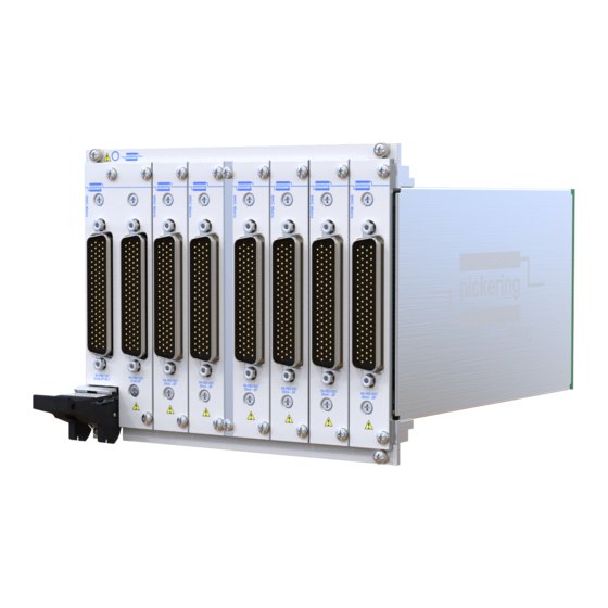
- Page 9 • Supported by PXI or LXI Chassis • Supported by eBIRST ™ • 3 Year Warranty X1.2 X1.1 X1.3 X2.2 The 40-592A FIBO (Fault Insertion Break-Out) Matrix Module X2.1 X2.3 is a large-scale high density switching matrix based on the Pickering BRIC™ format. X80.2 X80.1 X80.3...
- Page 10 BRIC High Density FIBO Matrix – 40-592A Relay Type Width and Dimensions The 40-592A is fitted with high performance instrumentation Four or eight slot 3U PXI module (CompactPCI). grade ruthenium sputtered reed relays. These offer very long life 3D models for these modules in a variety of popular file formats are with good low level switching performance and excellent contact available on request.
- Page 11 Dual 124x4 matrix 40-592A-014 40-592A-114 Mating Connectors & Cabling Dual 155x4 matrix 40-592A-115 For connection accessories for the 40-592A range please refer to the 90-006D 78-pin D-type Connector Accessories data sheet Dual 186x4 matrix 40-592A-116 where a complete list and documentation can be found for...
- Page 12 We provide a full range of supporting cable and connector solutions for all our switching products—20 connector families with 1200+ products. We offer everything from simple mating connectors to complex cables assemblies and terminal blocks. All assemblies are manufactured by Pickering and are guaranteed to mechanically and electrically mate to our modules. Connectors & Backshells...
- Page 13 BRIC High Density FIBO Matrix – 40-592A Programming Pickering provide kernel, IVI and VISA (NI & Keysight) drivers which are compatible with all Microsoft supported versions of Windows and popular older versions. For a list of all supporting operating systems, please see: pickeringtest.com/os...
- Page 14 SECTION 1 - TECHNICAL SPECIFICATION pickering THIS PAGE INTENTIONALLY BLANK BRIC HIGH DENSITY FIBO MATRIX MODULE (40-592A) Page 1.6...
-
Page 15: Technical Description
High Density Matrix Daughter Cards. The chassis is provided with cooling slots, top and bottom. The backplane provides mounting for the 50-pin connectors (into which the Matrix Daughter Cards plug) and Control logic. Figure 2.1 - 40-592A BRIC4 Chassis Architecture BRIC HIGH DENSITY FIBO MATRIX MODULE (40-592A) -
Page 16: Functional Description
The matrix relays are energised via control signals from the relay drivers, which are addressed by the PCI bridge U2 and FGPA U4 mounted on the Backplane, to output the required signal. The PCI Bridge U1 is configured by EEPROM U1 and the FGPA by U6. BRIC HIGH DENSITY FIBO MATRIX MODULE (40-592A) Page 2.2... - Page 17 The 8-Slot Backplane is fitted with 8 connectors J2 to J9 RELAY DRIVERS 8 Matrix Daughtercard assemblies are U1 TO U10 fitted to the 8-Slot Backplane MEZZANINE BOARD Figure 2.2 - 40-592A BRIC High Density FIBO Module: Functional Block Diagram BRIC HIGH DENSITY FIBO MATRIX MODULE (40-592A) Page 2.3...
-
Page 18: Fault Insertion Examples Using The Fibo Matrix
80x4 Fault Matrix Fault Insertion Example: Open Circuit on Break-Out 2 Fault Insertion Example 1: Open Circuit on Breakout 2 of a Dual 80x4 FIBO High Density Matrix Module With 3-pin Breakout BRIC HIGH DENSITY FIBO MATRIX MODULE (40-592A) Page 2.4... -
Page 19: X248.2
Fault Insertion Example: Signal Short to Ground Using Y2 With Breakout 2 Connection Open Fault Insertion Example 3: Signal Short to Ground Using Y2 With Breakout 2 Connection Open Using a Dual 248x4 FIBO High Density Matrix Module With 2-pin Breakout BRIC HIGH DENSITY FIBO MATRIX MODULE (40-592A) Page 2.5... -
Page 20: Y1 Y5
Fault Insertion Example: Routing Signals To Two UUTs For Comparison Fault Insertion Example 5: Routing Signals to Two UUTs For Comparison Using a Dual 80x4 FIBO High Density Matrix Module With 3-pin Breakout BRIC HIGH DENSITY FIBO MATRIX MODULE (40-592A) Page 2.6... - Page 21 Fault Insertion Example: Adding Series Resistance Into Break-Out 1 Using Y1, Y5 Fault Insertion Example 7: Adding a Series Resistance Into Breakout 1 Using Y1 and Y5 On a Dual 248x4 FIBO High Density Matrix Module With 2-pin Breakout BRIC HIGH DENSITY FIBO MATRIX MODULE (40-592A) Page 2.7...
- Page 22 SECTION 2 - TECHNICAL DESCRIPTION pickering THIS PAGE INTENTIONALLY BLANK BRIC HIGH DENSITY FIBO MATRIX MODULE (40-592A) Page 2.8...
-
Page 23: Installation
Modular products require installation in a suitable PXI/LXI chassis. The module is designed for indoor use only. PREOPERATION CHECKS (UNPACKING) 1. Check the module for transport damage and report any damage immediately to Pickering Interfaces. Do not attempt to install the product if any damage is evident. -
Page 24: Hardware Installation
For a system comprising more than one chassis, turn ON the last chassis in the system followed by the penultimate, etc, and finally turn ON the external controller or chassis containing the system controller. 9. For Pickering Interfaces modular LXI installation there is no requirement to use any particular power up sequence. -
Page 25: Testing Operation
Figure 3.2 - General Soft Front Panel Icon A selector panel will appear, listing all installed Pickering PCI, PXI or LXI switch cards and resistor cards. Click on the card you wish to control, and a graphical control panel is presented allowing operation of the card. - Page 26 SECTION 3 - INSTALLATION pickering THIS PAGE INTENTIONALLY BLANK BRIC HIGH DENSITY FIBO MATRIX MODULE (40-592A) Page 3.4...
-
Page 27: Programming Guide
SECTION 4 - PROGRAMMING PROGRAMMING OPTIONS FOR PICKERING INTERFACES PXI MODULES For information on the installation and use of drivers and the programming of Pickering’s products in various software environments, please refer to the Software User Manual. This is available as a download from: https://www.pickeringtest.com/support/software-drivers-and-downloads... -
Page 28: Module Architecture
The Following description applies to the 40-592A-114 (Dual 124x4 FIBO Matrix with 2-pin Breakout) other modules in the 40-592A range have the same architecture, but with different numbers of bits in the controlling sub-units. The 2-pin breakout version of the 40-592A consists of 3 Sub-units. SUB-UNIT 1 and SUB-UNIT 2 are (124x4) MATRICES whereas SUB-UNIT 3 consists of 124 Isolation Switches. - Page 29 The Following description applies to the 40-592A-108 (Dual 160x4 FIBO Matrix with 3-pin Breakout) other modules in the 40-592A range have the same architecture, but with different numbers of bits in the controlling sub-units. The 3-pin breakout versions of the 40-592A consists of 4 Sub-units. SUB-UNIT 1 and SUB-UNIT 2 are (160x4) MATRICES whereas SUB-UNIT 3 consists of 160 Isolation Switches and SUB-UNIT 4 contains the 160 Changeover Switches.
-
Page 30: Using The Module Under Ivi
SECTION 4 - PROGRAMMING GUIDE pickering USING THE MODULE UNDER IVI - 2-PIN BREAKOUT Figure 4.2 below displays the IVI channel names for the 40-592A-114 (Dual 124x4 Matrix with 2-pin Breakout). ComC1 ncC1 X1.1 X1.2 ComC2 ncC2 X2.1 X2.2 ComC124... - Page 31 SECTION 4 - PROGRAMMING GUIDE pickering 40-592A-114 IVI Channel Name Look-Up Table - Continued IVI Channel IVI Channel IVI Channel IVI Channel Name Name Name Name Name Name Name Name X25.1 xA25 X51.1 xA51 X77.1 xA77 X103.1 xA103 X25.2 xB25 X51.2...
- Page 32 SECTION 4 - PROGRAMMING GUIDE pickering USING THE MODULE UNDER IVI - 3-PIN BREAKOUT Figure 4.3 below displays the IVI channel names for the 40-592A-108 (Dual 160x4 Matrix with 3-pin Breakout). ncD1 ComC1 ncC1 ComD1 X1.2 X1.1 noD1 X1.3 ncD2...
- Page 33 SECTION 4 - PROGRAMMING GUIDE pickering 40-592A-108 IVI Channel Name Look-Up Table - Continued IVI Channel IVI Channel IVI Channel IVI Channel Name Name Name Name Name Name Name Name X22.2 ncD22 X40.1 xA40 X57.3 noD57 X75.2 ncD75 X22.3 noD22 X40.2...
- Page 34 SECTION 4 - PROGRAMMING GUIDE pickering 40-592A-108 IVI Channel Name Look-Up Table - Continued IVI Channel IVI Channel IVI Channel IVI Channel Name Name Name Name Name Name Name Name X93.1 xA93 X110.3 noD110 X128.2 ncD128 X146.1 xA146 X93.2 ncD93 X111.1...
-
Page 35: Using Direct I/O Driver Or Visa Driver
This section provides some code fragments which show how to control the Fault Insertion Breakout (FIBO) BRIC using the Direct I/O Driver or the VISA Driver. The module 40-592A-114 (Dual 124x4 Matrix with 2-pin Breakout) is shown. Other modules in the range operate in the same way but with different sub-unit/bit allocations, refer to the "Module Architecture"... - Page 36 = 1; // Operates Isolation Switch PIL_WriteSub( card_num, sub_unit, data); sub_unit = 1; // 124x4 MATRIX data[0] = 1; // Connects Y1 -> X1.1 data[0] = 0; // Disconnects Y1 -> X1.1 PIL_WriteSub( card_num, sub_unit, data); BRIC HIGH DENSITY FIBO MATRIX MODULE (40-592A) Page 4.10...
- Page 37 = 1; // Operates Isolation Switch pipx40_setChannelPattern( vi, sub_unit, data); sub_unit = 1; // 124x4 MATRIX data[0] = 1; // Connects Y1 -> X1.1 data[0] = 0; // Disconnects Y1 -> X1.1 pipx40_setChannelPattern( vi, sub_unit, data); BRIC HIGH DENSITY FIBO MATRIX MODULE (40-592A) Page 4.11...
-
Page 38: Using Pickering Drivers In Labview
USING PICKERING DRIVERS IN LabVIEW Most Pickering drivers include a LabVIEW wrapper to permit full operation of the Pickering product from the LabVIEW environment. These wrappers are normally installed to the current LabVIEW folder system during installation of the Pickering driver. -
Page 39: Connector Information
— — — — — — — Figure 5.1 - Pinout for Versions of The 40-592A High Density FIBO Matrix With 3-Pin Breakout - Daughter Board 1 40-592A Daughter Board 2 - 78-pin Male D-type Signal Signal Signal Signal Number... - Page 40 — — — — — — — Figure 5.3 - Pinout for Versions of The 40-592A High Density FIBO Matrix With 3-Pin Breakout - Daughter Board 3 40-592A Daughter Board 4 - 78-pin Male D-type Signal Signal Signal Signal Number...
- Page 41 — — — — — — — Figure 5.5 - Pinout for Versions of The 40-592A High Density FIBO Matrix With 3-Pin Breakout - Daughter Board 5 40-592A Daughter Board 6 - 78-pin Male D-type Signal Signal Signal Signal Number...
- Page 42 — — — — — — — Figure 5.7 - Pinout for Versions of The 40-592A High Density FIBO Matrix With 3-Pin Breakout - Daughter Board 7 40-592A Daughter Board 8 - 78-pin Male D-type Signal Signal Signal Signal Number...
- Page 43 X31.2 — — — — — — Figure 5.9 - Pinout for Versions of The 40-592A High Density FIBO Matrix With 2-Pin Breakout - Daughter Board 1 40-592A Daughter Board 2 - 78-pin Male D-type Signal Signal Signal Signal Number...
- Page 44 — — — — — — — Figure 5.11 - Pinout for Versions of The 40-592A High Density FIBO Matrix With 2-Pin Breakout - Daughter Board 3 40-592A Daughter Board 4 - 78-pin Male D-type Signal Signal Signal Signal Number...
- Page 45 — — — — — — — Figure 5.13 - Pinout for Versions of The 40-592A High Density FIBO Matrix With 2-Pin Breakout - Daughter Board 5 40-592A Daughter Board 6 - 78-pin Male D-type Signal Signal Signal Signal Number...
- Page 46 — — — — — — — Figure 5.15 - Pinout for Versions of The 40-592A High Density FIBO Matrix With 2-Pin Breakout - Daughter Board 7 40-592A Daughter Board 8 - 78-pin Male D-type Signal Signal Signal Signal Number...
-
Page 47: Trouble Shooting
PCI configuration, highlighting any potential configuration problems. Specific details of all installed Pickering switch cards are included. All the installed Pickering switch cards should be listed in the “Pilpxi information” section - if one or more cards is missing it may be possible to determine the reason by referring to the PCI configuration dump contained in the report, but interpretation of this information is far from straightforward, and the best course is to contact Pickering support: support@pickeringtest.com, if possible... - Page 48 SECTION 6 - TROUBLE SHOOTING pickering THIS PAGE INTENTIONALLY BLANK BRIC HIGH DENSITY FIBO MATRIX MODULE (40-592A) Page 6.2...
-
Page 49: Maintenance Information
For PXI modules which are supported in one of Pickering Interfaces’ Modular LXI Chassis (such as the 60-102B and 60-103B) no module software update is required. If the module was introduced after the LXI chassis was manufactured the module may not be recognized, in this case the chassis firmware may need upgrading. -
Page 50: Pcb Layout Diagrams
Replacement of relays should only be carried out by qualified personnel using the correct equipment. If qualified personnel are not available, or the location of a defective relay cannot be positively determined it is recommended that the module is returned to Pickering Interfaces or a replacement daughter card is ordered. - Page 51 SECTION 7 - MAINTENANCE INFORMATION pickering TABLE 7.1 - 40-592A 2-Pin Breakout Versions - Daughter Board 1 Relay Look-Up Table Crosspoint Crosspoint Crosspoint Switch Relay Relay Relay Relay Function Isolation X1 Isolation X2 Isolation X3 Isolation X4 Isolation X5 Isolation X6...
- Page 52 SECTION 7 - MAINTENANCE INFORMATION pickering TABLE 7.2 - 40-592A 2-Pin Breakout Versions - Mezzanine Board 1 Relay Look-Up Table Crosspoint Crosspoint Crosspoint Crosspoint Crosspoint Relay Relay Relay Relay Relay BRIC HIGH DENSITY FIBO MATRIX MODULE (40-592A) Page 7.4...
- Page 53 SECTION 7 - MAINTENANCE INFORMATION pickering TABLE 7.3 - 40-592A 2-Pin Breakout Versions - Daughter Board 2 Relay Look-Up Table Crosspoint Crosspoint Crosspoint Switch Relay Relay Relay Relay Function Isolation X32 Isolation X33 Isolation X34 Isolation X35 Isolation X36 Isolation X37...
- Page 54 SECTION 7 - MAINTENANCE INFORMATION pickering TABLE 7.4 - 40-592A 2-Pin Breakout Versions - Mezzanine Board 2 Relay Look-Up Table Crosspoint Crosspoint Crosspoint Crosspoint Crosspoint Relay Relay Relay Relay Relay BRIC HIGH DENSITY FIBO MATRIX MODULE (40-592A) Page 7.6...
- Page 55 SECTION 7 - MAINTENANCE INFORMATION pickering TABLE 7.5 - 40-592A 2-Pin Breakout Versions - Daughter Board 3 Relay Look-Up Table Crosspoint Crosspoint Crosspoint Switch Relay Relay Relay Relay Function Isolation X63 Isolation X64 Isolation X65 Isolation X66 Isolation X67 Isolation X68...
- Page 56 SECTION 7 - MAINTENANCE INFORMATION pickering TABLE 7.6 - 40-592A 2-Pin Breakout Versions - Mezzanine Board 3 Relay Look-Up Table Crosspoint Crosspoint Crosspoint Crosspoint Crosspoint Relay Relay Relay Relay Relay BRIC HIGH DENSITY FIBO MATRIX MODULE (40-592A) Page 7.8...
- Page 57 SECTION 7 - MAINTENANCE INFORMATION pickering TABLE 7.7 - 40-592A 2-Pin Breakout Versions - Daughter Board 4 Relay Look-Up Table Crosspoint Crosspoint Crosspoint Switch Relay Relay Relay Relay Function Isolation X94 Isolation X95 Isolation X96 Isolation X97 Isolation X98 Isolation X99...
- Page 58 SECTION 7 - MAINTENANCE INFORMATION pickering TABLE 7.8 - 40-592A 2-Pin Breakout Versions - Mezzanine Board 4 Relay Look-Up Table Crosspoint Crosspoint Crosspoint Crosspoint Crosspoint Relay Relay Relay Relay Relay BRIC HIGH DENSITY FIBO MATRIX MODULE (40-592A) Page 7.10...
- Page 59 SECTION 7 - MAINTENANCE INFORMATION pickering TABLE 7.9 - 40-592A 2-Pin Breakout Versions - Daughter Board 5 Relay Look-Up Table Crosspoint Crosspoint Crosspoint Switch Relay Relay Relay Relay Function Isolation X125 Isolation X126 Isolation X127 Isolation X128 Isolation X129 Isolation X130...
- Page 60 SECTION 7 - MAINTENANCE INFORMATION pickering TABLE 7.10 - 40-592A 2-Pin Breakout Versions - Mezzanine Board 5 Relay Look-Up Table Crosspoint Crosspoint Crosspoint Crosspoint Crosspoint Relay Relay Relay Relay Relay BRIC HIGH DENSITY FIBO MATRIX MODULE (40-592A) Page 7.12...
- Page 61 SECTION 7 - MAINTENANCE INFORMATION pickering TABLE 7.11 - 40-592A 2-Pin Breakout Versions - Daughter Board 6 Relay Look-Up Table Crosspoint Crosspoint Crosspoint Switch Relay Relay Relay Relay Function Isolation X156 Isolation X157 Isolation X158 Isolation X159 Isolation X160 Isolation X161...
- Page 62 SECTION 7 - MAINTENANCE INFORMATION pickering TABLE 7.12 - 40-592A 2-Pin Breakout Versions - Mezzanine Board 6 Relay Look-Up Table Crosspoint Crosspoint Crosspoint Crosspoint Crosspoint Relay Relay Relay Relay Relay BRIC HIGH DENSITY FIBO MATRIX MODULE (40-592A) Page 7.14...
- Page 63 SECTION 7 - MAINTENANCE INFORMATION pickering TABLE 7.13 - 40-592A 2-Pin Breakout Versions - Daughter Board 7 Relay Look-Up Table Crosspoint Crosspoint Crosspoint Switch Relay Relay Relay Relay Function Isolation X187 Isolation X188 Isolation X189 Isolation X190 Isolation X191 Isolation X192...
- Page 64 SECTION 7 - MAINTENANCE INFORMATION pickering TABLE 7.14 - 40-592A 2-Pin Breakout Versions - Mezzanine Board 7 Relay Look-Up Table Crosspoint Crosspoint Crosspoint Crosspoint Crosspoint Relay Relay Relay Relay Relay BRIC HIGH DENSITY FIBO MATRIX MODULE (40-592A) Page 7.16...
- Page 65 SECTION 7 - MAINTENANCE INFORMATION pickering TABLE 7.15 - 40-592A 2-Pin Breakout Versions - Daughter Board 8 Relay Look-Up Table Crosspoint Crosspoint Crosspoint Switch Relay Relay Relay Relay Function Isolation X218 Isolation X219 Isolation X220 Isolation X221 Isolation X222 Isolation X223...
- Page 66 SECTION 7 - MAINTENANCE INFORMATION pickering TABLE 7.16 - 40-592A 2-Pin Breakout Versions - Mezzanine Board 8 Relay Look-Up Table Crosspoint Crosspoint Crosspoint Crosspoint Crosspoint Relay Relay Relay Relay Relay BRIC HIGH DENSITY FIBO MATRIX MODULE (40-592A) Page 7.18...
- Page 67 SECTION 7 - MAINTENANCE INFORMATION pickering TABLE 7.17 - 40-592A 3-Pin Breakout Versions - Daughter Board 1 Relay Look-Up Table Relay Relay Relay Relay Switch Function Switch Function Switch Function Switch Function Isolation X1.1 Isolation X6.1 Isolation X11.1 Isolation X16.1 Breakout X1.2...
- Page 68 SECTION 7 - MAINTENANCE INFORMATION pickering TABLE 7.19 - 40-592A 3-Pin Breakout Versions - Daughter Board 2 Relay Look-Up Table Relay Relay Relay Relay Switch Function Switch Function Switch Function Switch Function Isolation X21.1 Isolation X26.1 Isolation X31.1 Isolation X36.1 Breakout X21.2...
- Page 69 SECTION 7 - MAINTENANCE INFORMATION pickering TABLE 7.21 - 40-592A 3-Pin Breakout Versions - Daughter Board 3 Relay Look-Up Table Relay Relay Relay Relay Switch Function Switch Function Switch Function Switch Function Isolation X41.1 Isolation X46.1 Isolation X51.1 Isolation X56.1 Breakout X41.2...
- Page 70 SECTION 7 - MAINTENANCE INFORMATION pickering TABLE 7.23 - 40-592A 3-Pin Breakout Versions - Daughter Board 4 Relay Look-Up Table Relay Relay Relay Relay Switch Function Switch Function Switch Function Switch Function Isolation X61.1 Isolation X66.1 Isolation X71.1 Isolation X76.1 Breakout X61.2...
- Page 71 SECTION 7 - MAINTENANCE INFORMATION pickering TABLE 7.25 - 40-592A 3-Pin Breakout Versions - Daughter Board 5 Relay Look-Up Table Relay Relay Relay Relay Switch Function Switch Function Switch Function Switch Function Isolation X81.1 Isolation X86.1 Isolation X91.1 Isolation X96.1 Breakout X81.2...
- Page 72 SECTION 7 - MAINTENANCE INFORMATION pickering TABLE 7.27 - 40-592A 3-Pin Breakout Versions - Daughter Board 6 Relay Look-Up Table Relay Relay Relay Relay Switch Function Switch Function Switch Function Switch Function Isolation X101.1 Isolation X106.1 Isolation X111.1 Isolation X116.1 Breakout X101.2...
- Page 73 SECTION 7 - MAINTENANCE INFORMATION pickering TABLE 7.29 - 40-592A 3-Pin Breakout Versions - Daughter Board 7 Relay Look-Up Table Relay Relay Relay Relay Switch Function Switch Function Switch Function Switch Function Isolation X121.1 Isolation X126.1 Isolation X131.1 Isolation X136.1 Breakout X121.2...
- Page 74 SECTION 7 - MAINTENANCE INFORMATION pickering TABLE 7.31 - 40-592A 3-Pin Breakout Versions - Daughter Board 8 Relay Look-Up Table Relay Relay Relay Relay Switch Function Switch Function Switch Function Switch Function Isolation X141.1 Isolation X146.1 Isolation X151.1 Isolation X156.1 Breakout X141.2...
- Page 75 RL62 RL54 RL46 RL79 RL71 RL63 RL55 RL47 RL80 RL72 RL64 RL56 RL48 RL85 RL81 RL86 RL82 RL87 RL83 RL84 RL88 Figure 7.1 - 40-592A Daughterboard - 2-Pin Breakout: Component Layout BRIC HIGH DENSITY FIBO MATRIX MODULE (40-592A) Page 7.27...
- Page 76 SECTION 7 - MAINTENANCE INFORMATION pickering RL13 RL17 RL14 RL18 RL10 RL15 RL19 RL11 RL16 RL20 RL12 Figure 7.2 - 40-592A Daughterboard - 3-Pin Breakout: Component Layout BRIC HIGH DENSITY FIBO MATRIX MODULE (40-592A) Page 7.28...
- Page 77 RL126 RL134 RL142 RL150 RL158 RL159 RL143 RL151 RL144 RL152 RL160 RL127 RL135 RL128 RL136 Figure 7.3 - 40-592A Mezzanine Board: Component Layout (Common to 2-Pin Breakout and 3-Pin Breakout Versions) BRIC HIGH DENSITY FIBO MATRIX MODULE (40-592A) Page 7.29...
-
Page 78: Card Removal From Bric
CARD REMOVAL FROM BRIC The following procedure should be followed for the extraction of a matrix relay card from the 40-592A BRIC module. The card extraction handle supplied with the module is required for this process as shown in Figure 7.5. It should be noted that individual matrix cards can be removed from the BRIC sub-chassis without removing the entire BRIC from the host chassis. - Page 79 4. Carefully pull the relay card free from the BRIC chassis using the extraction handle as shown in Figure 7.8. Once the card is removed the extraction handle can be unscrewed from the relay card’s connector. Figure 7.8 - Removing The Relay Card BRIC HIGH DENSITY FIBO MATRIX MODULE (40-592A) Page 7.31...
-
Page 80: Card Replacement
(Note: There is 0.5 mm approx of “free play” on the relay card between the back plane and the front panel. When tightening the front panel screws the inserted relay card could be pulled out about 0.5 mm. This does not effect the interconnection on the backplane) Tighten all screws. BRIC HIGH DENSITY FIBO MATRIX MODULE (40-592A) Page 7.32...
Need help?
Do you have a question about the 40-592A and is the answer not in the manual?
Questions and answers