Table of Contents
Advertisement
Quick Links
Advertisement
Table of Contents

Related Manuals for Skytron 3002 IMPULSE


Summary of Contents for Skytron 3002 IMPULSE
- Page 1 IMAGING TABLE OPERATORS MANUAL 3002 IMPULSE REV 6/05...
- Page 3 MODEL 3002 IMPULSE REV 6/05 Although current at the time of publication, SKYTRON’s policy of continuous development makes this manual subject to change without notice.
-
Page 5: Table Of Contents
TABLE OF CONTENTS Title Page EQUIPMENT LABELS AND SPECIFICATIONS ..................2 3002 Impulse Imaging Table Specifications ..................... 3 SPECIAL USER ATTENTION ........................ 4 SECTION I INTRODUCTION ......................... 6 1-1. General ............................6 1-2. Power Requirements ........................6 1-3. Pendant Control Unit ........................7 1-4. -
Page 6: Equipment Labels And Specifications
EQUIPMENT LABELS AND SPECIFICATIONS FUSE TYPE 10 AMP, FAST ACTING (FA) INDICATES DANGEROUS VOLTAGE, 120 V, 60 Hz CLASS I DEFIBRILLATION PROOF, TYPE B EQUIPMENT- IPX4 RATED. INTERNALLY POWERED EQUIPMENT TYPE B EQUIPMENT PROTECTIVE GROUNDING. IN ORDER TO ENSURE PROPER GROUNDING RELIABILITY, THIS TABLE MUST BE CONNECTED TO A PROPERLY GROUNDED HOSPITAL GRADE OUTLET. -
Page 7: 3002 Impulse Imaging Table Specifications
3002 Impulse Imaging Table Specifications TOP VIEW 30" 19.7" 17.625" 33" 82.5" 21.875" 42" MAX 28" MIN 5.625" 8.125" 40.5" 19" SIDE VIEW END VIEW ENTELA PENDING Electrical Specifications TO UL2601-1, Power requirements 120 VAC, 60Hz, 450 Watts CAN/CSA601.1, IEC 60601-2-46... -
Page 8: Special User Attention
SPECIAL USER ATTENTION NOTE Certain accessories can be damaged when chang- ing the position of the table top. Always look first to Activating any function button will acti- see if a desired movement is going to interfere with vate the brake system. Using the TABLE any accessories in use. - Page 9 WARNING WARNING The antistatic properties of the table are To maximize patient safety, utilize dependent on the use of the original pad proper restraint methods during extreme set which was furnished with the table Trendelenburg and lateral tilt position- or an alternate approved replacement. ing.
-
Page 10: Section I Introduction
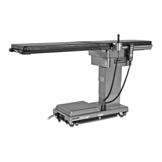
CAPACITY TAG Figure 1-1. 3002 Impulse 1-2. Power Requirements 1-1. General The 3002 Impulse Imaging Table requires a SKYTRON’s 3002 Impulse Imaging Table is electro- 120VAC, 60 Hz electrical power supply. The table hydraulically operated. See figure 1-1. is equipped with a 15 foot long removable power cord with a three prong, hospital grade plug. -
Page 11: Pendant Control Unit
1-4. Floor Lock/Brake System 1-3. Pendant Control Unit The floor lock/brake system consists of four self- The hand-held pendant control unit (figure 1-3) has leveling, hydraulic brake cylinders which raise and a non-slip rubber cover which assures a positive support the table base off from the casters. Press grip during use. -
Page 12: Section Ii Operation
SECTION II OPERATION NOTE 2-1. Electrical Power An equalization grounding terminal is located under the main power panel. This is provided as an alternate path- WARNING way to reduce the risk of static shock hazards. Always follow recommended DO NOT use the table in the presence grounding procedures to ensure patient of FLAMMABLE GASES (Flammable and staff safety. -
Page 13: Trendelenburg
NOTE Press the BRAKE-UNLOCK button on the pendant Return from Trendelenburg positioning control to release the four self-leveling brake feet in with a 500 pound patient positioned with order to move the table. See figure 2-3. The brake head away from elevation column and delay circuit automatically retracts the brake sys- Top Slide positioned fully toward the tem with just one press of the BRAKE-UNLOCK... -
Page 14: Top Slide
e. Top Slide. To achieve Longitudinal Top Slide, f. Return To Level. To return the table top to a press the appropriate SLIDE button (figure 2-7). level position, press the LEVEL button (figure 2-9). Longitudinal Top Slide of up to 20" may be obtained. P O W E R TRENDELENBURG P O W E R... - Page 15 The two respective LED indicators will be lighted The multi-directional control will accept 8 different directional commands. One each left and right green or red depending on the selection. The speed lateral movement, one each longitudinal movement LED will be green when in high speed and red when in low speed.
-
Page 16: Emergency Brake Release
During transfer, DO NOT seat the pa- tient at the distal end of the table. Table Consult manufacturer's instructions stability may be compromised. when using high frequency surgical equipment, cardiac defibrillator and car- Lithotomy positioning is NOT ADVISED diac defibrillator monitors. for the 3002 Impulse table. - Page 17 PIVOTING CARBON FIBER CLAMP-ON ARMBOARD (2) P/N: 2-060-03 RESTRAINT STRAP P/N: 6-010-41-B 6" ACCESSORY RAIL CLAMP P/N: 6-070-06 Figure 2-15. STANDARD ARMBOARD (2) P/N: 2-010-02 RESTRAINT STRAP P/N: 6-010-41-B 6" ACCESSORY RAIL CLAMP P/N: 6-070-06 Figure 2-16.
-
Page 18: Section Iii Maintenance
The following preventive maintenance checks and Always follow OSHA blood-borne patho- services are recommended to ensure the service- gens standards for protective clothing, ability and proper operation of your SKYTRON including gloves, masks and eye pro- Imaging Table. tection when cleaning the table. -
Page 19: Service
Service instructions and parts are available from SKYTRON. To obtain service instructions, replacement parts, factory service or preventive maintenance con- tracts, contact the SKYTRON representative listed below. Or contact: SKYTRON 5000 - 36th Street S.E. - Page 24 5000 36th Street S.E., Grand Rapids, MI 49512 1-800-SKYTRON or 1-616-957-0500 • FAX 1-616-957-5053...
Need help?
Do you have a question about the 3002 IMPULSE and is the answer not in the manual?
Questions and answers