
Related Manuals for Gree GMV-Y96WM/A-F(U)


Summary of Contents for Gree GMV-Y96WM/A-F(U)
- Page 1 Owner's Manual Original Instructions Commercial Air Conditioners Photovoltaic Multi VRF Models: GMV-Y96WM/A-F(U)
- Page 2 Preface Gree Photovoltaic Multi VRF System, with the most advanced technologies in the world, uses eco-friendly refrigerant R410A as its cooling medium. For correct installation and operation, please read this manual carefully. This is the safety alert symbol. It is used to alert you to potential personal injury hazards.
- Page 3 Exception Clauses Manufacturer will bear no responsibilities when personal injury or property loss is caused by the following reasons: Damage the product due to improper use or misuse of the product; (2) Alter, change, maintain or use the product with other equipment without abiding by the instruction manual of manufacturer;...
- Page 4 Contents 1 Safety Precautions .................... 1 2 Product Introduction ..................2 2.1 Names of Main Parts ....................2 2.2 Combinations of Indoor and Outdoor Units ..............2 2.3 The Range of Production Working Temperature ............3 3 Preparation before Installation ................. 4 3.1 Standard Parts ......................
-
Page 5: Safety Precautions
(19) User is not allowed to repair the unit. Fault service may cause electric shock or fire accidents. Please contact Gree appointed service center for help. (20) Before installation, please check if the power supply is in accordance with the requirements specified on the nameplate. -
Page 6: Product Introduction
(27) If anything abnormal happens (such as burning smell), please power off the unit and cut off the main power supply, and then immediately contact Gree appointed service center. If abnormality keeps going, the unit might be damaged and lead to electric shock or fire. -
Page 7: The Range Of Production Working Temperature
Photovoltaic Multi VRF Fig.2.2.1 Fig.2.2.1 is the combination view of the ODU of Modular DC Inverter Multi VRF System and the IDU of Multi VRF System. IDU can be cassette type, one-way cassette type, wall-mounted type, duct type, etc. When any one IDU receives operation signal, ODU will start to work according to the capacity;... -
Page 8: Preparation Before Installation
Photovoltaic Multi VRF 3 Preparation before Installation NOTICE! The picture is only used for reference and the actual product prevails. Unit: mm(in.). 3.1 Standard Parts Please use the following standard parts supplied by Gree. Parts for Outdoor Unit Number Name Picture... - Page 9 Photovoltaic Multi VRF Space dimension for dual-module unit Unit: mm(in.) Fig.3.2.2 Space dimension for three-module unit Unit: mm(in.) Fig.3.2.3...
- Page 10 Photovoltaic Multi VRF (2) When there is wall (or similar obstruction) above the unit, keep the distance between the unit top and the wall at least 3000mm(118-1/8in.) or above. When the unit is located in a totally open space with no obstructions in four directions, keep the distance between the unit top and wall at least 1500mm(59in.) or above (See Fig.3.2.4).
- Page 11 Photovoltaic Multi VRF (3) Space dimension for multiple-module unit For keeping good ventilation, make sure there is no obstruction above the unit. When the unit is located at a half-open space (front and left/right side is open), install the unit as per the same or opposite direction. Unit: mm(in.) Fig.3.2.6...
- Page 12 Photovoltaic Multi VRF Fig.3.2.7 (4) Considering the seasonal wind in outdoor unit installation Anti-monsoon installation requirement for unit not connecting exhaust duct Fig.3.2.8...
- Page 13 Photovoltaic Multi VRF Fig.3.2.9 Anti-monsoon installation requirement for unit connecting exhaust duct Fig.3.2.10 (5) Considering snow in outdoor unit installation Fig.3.2.11...
-
Page 14: Piping Work Requirements
Photovoltaic Multi VRF 3.3 Piping Work Requirements There should be no fall among outdoor modules. Refer to the table below for piping work requirements. R410A Refrigerant System Outer Diameter mm(in.) Wall Thickness mm(in.) Type Φ6.35(1/4) ≥0.8(1/32) Φ9.52(3/8) ≥0.8(1/32) Φ12.7(1/2) ≥0.8(1/32) Φ15.9(5/8) ≥1.0(3/76) Φ19.05(3/4) -
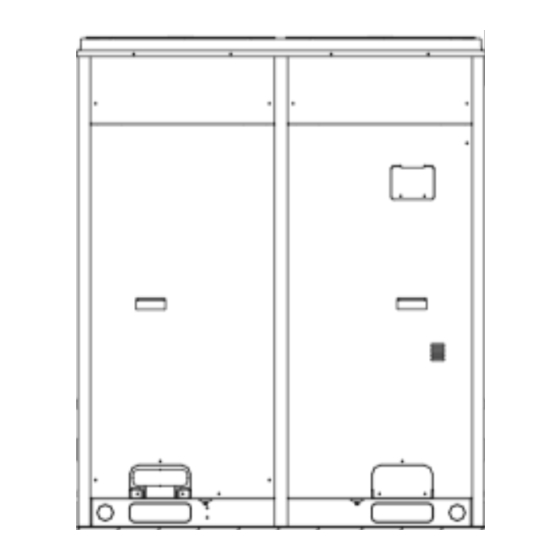
Page 15: Physical Dimension Of The Outdoor Unit And Mounting Hole
Photovoltaic Multi VRF 4.2 Physical Dimension of the Outdoor Unit and Mounting Hole Outline and Physical Dimention of GMV-Y96WM/A-F(U) Unit: mm(in.) Fig.4.2.1... -
Page 16: Connection Pipe
Photovoltaic Multi VRF 4.3 Connection Pipe 4.3.1 Schematic Diagram of Piping Connection Fig.4.3.1 4.3.2 Schematic Diagram of Piping Sequence GMV-Y96WM/A-F(U) Fig.4.3.2... - Page 17 Photovoltaic Multi VRF 4.3.3 Allowable pipe length and drop height among indoor and outdoor units Y type branch joint is adopted to connect indoor and outdoor units. Connecting method is shown in the figure below. Remark: Equivalent length of one Y-type manifold is about 0.5m(1-3/4ft.). Unit: m(ft.) Fig.4.3.3 L10: Length from the first branch to the farthest IDU;...
- Page 18 Photovoltaic Multi VRF Allowable Value R410A Refrigerant System Fitting Pipe m(ft.) Equivalent length from the first branch to the furthest ≤40(131-1/4) L6+L7+L8+L9+j piping (1) Height difference ≤90(295-1/4) —— Outdoor unit at upper(2) between outdoor unit ≤90(295-1/4) —— Outdoor unit at lower(2) and indoor unit ≤30(98-2/4) ——...
- Page 19 Photovoltaic Multi VRF Pipe size of basic outdoor module is shown as follows: Pipe between ODU and the first branch of IDU Basic Module Liquid Pipe mm(in.) Gas Pipe mm(in.) Φ22.2(7/8) Φ9.52(3/8) GMV-Y96WM/A-F(U) (2) Fitting pipe between the first manifold from indoor unit and the end manifold from outdoor unit Fig.4.3.5 Pipe between ODU and the first branch of IDU...
- Page 20 Photovoltaic Multi VRF Fig.4.3.6(b) R410A Refrigerant System Total capacity of downstream indoor unit(s) C (KBtu/h) Model C<68 FQ01A/A 68≤C≤102 FQ01B/A Y-type Manifold 102<C≤239 FQ02/A 239<C FQ03/A C≤136 FQ14/H1 C≤232 T-type Manifold FQ18/H1 232<C FQ18/H2 (4) Fitting pipe between manifolds Pipe size (between two manifolds at indoor unit side) is based on the total capacity of upstream indoor unit(s).
-
Page 21: Installation Of The Connection Pipe
Photovoltaic Multi VRF Dimension of the pipe of indoor branch Total capacity of downstream indoor unit(s) C(Btu/h) Gas Pipe mm(in.) Liquid Pipe mm(in.) Φ34.9(1-3/8) Φ15.9(5/8) 216000<C≤240000 Φ34.9(1-3/8) Φ19.05(3/4) 240000<C≤336000 Φ41.3(1-5/8) Φ19.05(3/4) 336000<C (5) Fitting pipe between indoor unit and manifold Manifold should be matched with fitting pipe of indoor unit. - Page 22 Photovoltaic Multi VRF (4) Please use a torque wrench to connect union nut on the indoor unit. See Fig.4.4.1. Fig.4.4.1 1) Align the expansion end of copper pipe with the center of threaded joint. Tighten the flare nuts with your hands. 2) Tighten the flare nuts with torque wrench until you hear "click"...
- Page 23 Photovoltaic Multi VRF with various copper pipe. Use pipe cutter to cut in the middle of the pipe section with different pipe size and deburr as well. See Fig. 4.4.3. Fig. 4.4.3 (3) Y-type manifold can be installed vertically or horizontally. Confirm the position and then weld the manifold pipe.
- Page 24 Photovoltaic Multi VRF 4.4.3 Installation and thermal insulation for pipeline (1) For multi VRF system, every copper pipe should be labeled so as to avoid misconnection. (2) Manifolds can be laid in the following ways: The length of a straight pipe between two manifolds cannot be less than 500 mm (19-11/16in.).
- Page 25 Photovoltaic Multi VRF (4) Suspend the header to the ceiling, and be sure to install the T-type manifold so that the outlet pipes are horizontal at the lower side. See Fig. 4.4.7. Fig.4.4.7 (5) Thermal insulation for pipeline 1) To avoid condensate or water leakage on connecting pipe, the gas pipe and liquid pipe must be wrapped with thermal insulating material and adhesive pipe for insulation from the air.
-
Page 26: Air Purging And Refrigerant Charge
Photovoltaic Multi VRF 3) Joints at indoor and outdoor units should be wrapped with insulating material and leave no clearance between pipe and wall. See Fig.4.4.8. Fig.4.4.8 4) Manifold attached foam can not be taken as insulating material. 5) When wrapping the tape, the later circle should cover half of the former one. Don’t wrap the tape so tightly, otherwise the insulation effect will be weakened. - Page 27 Photovoltaic Multi VRF than 1m(39-3/8in.), please refer to the following table for charging amount of refrigerant. (Liquid pipe prevails) How much additional refrigerant should be charged Total refrigerant charging amount R= Pipeline charging amount A + ∑charging amount B of every module (1) Pipeline charging amount Added refrigerant quantity A for piping = ∑Liquid pipe length ×...
- Page 28 Photovoltaic Multi VRF So, ΣB (Quantity of refrigerant added to each module) = 0kg (0pounds). Suppose that A (Quantity of refrigerant added to connection pipe) = ∑ Length of liquid pipe x Quantity of refrigerant added to liquid pipe per meter) = 5kg (11pounds). R (Quantity of added refrigerant in total) = 5+0=5kg (11+0=11pounds).
-
Page 29: Electric Wiring
Photovoltaic Multi VRF ① Flow direction of refrigerant leakage. ② Room for refrigerant leakage. Since the concentration of refrigerant is greater than that of air, pay attention to the spaces where the refrigerant may residue, for example, the basement. 4.6 Electric Wiring 4.6.1 Wiring precautions Wiring should conform to national rules. -
Page 30: Connection Of Power Cord
Photovoltaic Multi VRF Specification of circuit breaker and power cord is selected on the basis of unit’s maximum power (max. current). Specification of power cord is based on the working condition where ambient temperature is 40 º C (104° F) and multi-core cable with copper conductor(working temperature is 90 º C (194° F), e.g. power cable with YJV cross-linked copper, insulated PE and PVC sheath) is lying on the surface of slot. -
Page 31: System Communication
Photovoltaic Multi VRF 4.7 System Communication 4.7.1 Communication system include: (1) Communication among outdoor basic modules. (2) Communication between ODU and IDU. (3) Communication among IDUs. (4) Communication between IDU and wired controller. (5) Connection between IDU and light board receiver. (6) Communication between different refrigeration systems. -
Page 32: Communication Mode
Photovoltaic Multi VRF 4.7.2 Communication mode CAN bus mode is taken for communication between IDU and ODU and communication among IDUs. 4.7.3 Selection and connection mode of photovoltaic Multi VRF communication material 4.7.3.1 Select communication material NOTICE! If air conditioners are installed at places where there’s strong electromagnetic interference, the communication wire of IDU and wired controller must use shielded wire and the communication wire between IDU and IDU/ODU must use shielded twisted pair. - Page 33 Photovoltaic Multi VRF Fig.4.7.3 NOTICE! All of the selected communication wire must be consistent with local laws and regulations. 4.7.3.2 Connection mode of communication (1) All communication wires must be connected in series rather than in star. Fig.4.7.4 Fig.4.7.5...
- Page 34 Photovoltaic Multi VRF (2) All communication wires are connected by screws. Fig.4.7.6 (3) If a single communication wire is not long enough and needs to be connected, the connected joint must be welded or pressure-welded. Do not simply twist the wires together.
-
Page 35: Connection Method And Steps For System Communication
Photovoltaic Multi VRF 4.8 Connection Method and Steps for System Communication 4.8.1 Communication connection between IDU and ODU NOTICE! The centralized controller can be installed when it is necessary. Connect IDU and ODU via terminal D1/D2 of wiring board XT2. Below are the connection graphics of single unit: Fig.4.8.1 Communication wire and power cord must be separated. - Page 36 Photovoltaic Multi VRF 4.8.2 Communication connection between IDU and wired controller There are 4 kinds of connection between IDU and wired controller, as shown below: Fig.4.8.2 One wired controller controls one IDU Fig.4.8.3 Two wired controllers controls one IDU Fig.4.8.4 One wired controller controls multiple IDUs Fig.4.8.5 Two wired controllers control multiple IDUs...
- Page 37 Photovoltaic Multi VRF When two wired controllers control multiple IDUs, the wired controller can be connected to any one IDU, provided that the connected IDU is of the same series. Meanwhile, one and only one of the wired controllers must be set as a slave controller. At most 16 IDUs can be controlled by wired controllers and the connected IDUs shall be within a same IDU network.
- Page 38 Photovoltaic Multi VRF 4.8.3 Communication connection of central controlling units NOTICE! The centralized controller can be installed when it is necessary. Port connection G1 and G2 on the wiring board XT2 of master unit among each multi VRF system (see below) Fig.4.8.6...
-
Page 39: External Electrical Wiring Diagram
Photovoltaic Multi VRF 4.9 External Electrical Wiring Diagram Every unit should be equipped with a circuit breaker for short-circuit and overload protection. In general, circuit breaker is at OFF status. During operation, all indoor units and outdoor units belonging to the same system must be kept energized status. - Page 40 Photovoltaic Multi VRF Please strictly observe static protection specification while operating the device. Electric shock and fire hazard might lead to electrical leakage, before connecting PV and power grid, please make sure the AC has already safely grounded. Any operation of the device must be conducted by relevant professional electrician; if the device needs repairing, please contact relevant professional staff;...
- Page 41 Photovoltaic Multi VRF 4.10.2.2 Installation of PV battery component PV battery component shall be used after acceptance of relevant department of Party A. Common PV battery component is shown in the following fig. Fig.4.10.2 Handle with care during transportation to avoid collision of PV component and PV component, PV component and frame.
- Page 42 Photovoltaic Multi VRF 4.10.2.4 Installation and wiring of distribution equipment (read it according to your demand) Before installing the distribution equipment, open the box for inspection first, based on the device list, construction drawing and device technical material, check the main uint, attachment and spare parts of the device, product certificate, technical material and specification, to see if they are complete.
-
Page 43: Trial Run
Photovoltaic Multi VRF 5.2 Trial Run NOTICE! During debugging, one and only one module must be set as a master module. During debugging, one and only one IDU must be set as a master IDU. When no special requirement is needed, no need to set other functions. Unit can operate according to ex-factory settings. - Page 44 Photovoltaic Multi VRF (6) Description of each stage of debugging progress: Description of each stage of debugging progress —— Debugging code Progress code Status code LED1 LED2 LED3 Meaning progress Display Display Display Code code Code status status status light light light System is not debugged.
- Page 45 Photovoltaic Multi VRF Description of each stage of debugging progress —— Debugging code Progress code Status code LED1 LED2 LED3 Meaning progress Display Display Display Code code Code status status status System detects error in indoor components. XXXX is the project no. of XXXX the faulted IDU.
- Page 46 Photovoltaic Multi VRF Description of each stage of debugging progress —— Debugging code Progress code Status code LED1 LED2 LED3 Meaning progress Display Display Display Code code Code status status status Outdoor pipeline and valves are not light light light normal.
- Page 47 Photovoltaic Multi VRF Step 5: Find the module with “01” module address to be the master module. Hold SW7 button on the master module for at least 5s to enable debugging; Step 6: Wait. Unit will then start progress 01 and 02; in progress 01, if master unit is not correctly set, progress 01 will show the following errors: Debugging Code Progress Code...
- Page 48 Photovoltaic Multi VRF Step 8: in progress 04, the quantity of IDUs needs to be confirmed manually. Main board of each module will display: Debugging code Progress code Status code LED1 LED2 LED3 Progress Code Display status Code Display status Code Display status 04_Confirm the...
- Page 49 Photovoltaic Multi VRF Step 10: progress 06 is “Detect outdoor components” If no error is detected, system will display as below and then start next progress. —— Debugging code Progress code Status code LED1 LED2 LED3 Meaning progress Display Display Display Code code...
- Page 50 Photovoltaic Multi VRF Step 12: progress 08 is “Confirm preheated compressor” If more than 8h of preheat time is detected, system will display as below and start next progress. —— Debugging code Progress code Status code LED1 LED2 LED3 Meaning progress Display Display...
- Page 51 Photovoltaic Multi VRF Step 14: progress 10 is “Status judgments of outdoor valves before startup” If master unit displays below, status judgments are enabled. —— Debugging code Progress code Status code LED1 LED2 LED3 Meaning progress Display Display Display Code code Code status...
- Page 52 Photovoltaic Multi VRF If it’s confirmed, press SW7 confirmation button. Unit will display as below and start next progress. —— Debugging code Progress code Status code LED1 LED2 LED3 Meaning progress Display Display Display Code code Code status status status Manual calculation of 12_Status judgments of Light...
- Page 53 Photovoltaic Multi VRF —— Debugging code Progress code Status code LED1 LED2 LED3 Meaning progress Display Display Display Code code Code status status status System detects error in indoor pipeline. XXXX is the project no. of the faulted IDU. 3s later, error code U8 is XXXX Light Light...
- Page 54 Photovoltaic Multi VRF Reference of Debug Parameters of photovoltaic multi VRF System Debug item Parameter name Unit Reference ● System’s normal high pressure value is within 20~25º C(68~77° F) According to the change in ambient temp and system operational capacity, system’s high pressure value is 10~40 º...
-
Page 55: Common Malfunction And Troubleshooting
Photovoltaic Multi VRF Reference of Debug Parameters of photovoltaic multi VRF System Debug item Parameter name Unit Reference Current of fan motor 2 º C(° F) —— Ambient temp of IDU ● According to different ambient temp, for a same Inlet tube temp of º... - Page 56 Otherwise, there will be collision malfunction of the project codes. For detail operation methods, please refer to the GMV5 Installation and Maintenance Manual. If problem cannot be solved after checking the above items, please contact Gree service center and show phenomena and models.
-
Page 57: Error Indication
Photovoltaic Multi VRF 7 Error Indication Inquiry method of malfunction display: combine division number and content number to check the corresponding malfunction. Indoor: Error Code Content Error Code Content Malfunction of lower water Malfunction of IDU temperature sensor of water tank Malfunction of ambient temperature Protection of indoor fan sensor... - Page 58 Photovoltaic Multi VRF Error Code Content Error Code Content Over-current protection of Malfunction of casing top compressor 1 temperature sensor of compressor 1 Over-current protection of Malfunction of casing top compressor 2 temperature sensor of compressor 2 Over-current protection of Malfunction of exit tube temperature compressor 3 sensor of mode exchanger...
- Page 59 Photovoltaic Multi VRF Error Code Content Error Code Content Malfunction of drive temperature Phase-lacking of inverter compressor sensor of fan Malfunction of charging loop of driven Drive IPM high temperature of compressor protection of fan Failure startup of inverter Desynchronizing protection of compressor inverter fan AC current protection of inverter...
- Page 60 Photovoltaic Multi VRF Debugging: Error Code Content Error Code Content Preheat time of compressor is Alarm because ODU quantity is insufficient inconsistent Wrong setting of ODU’s capacity Abnormal communication of code/jumper cap converter Power supply phase sequence Emergency status of compressor protection Refrigerant-lacking protection Emergency status of fan...
-
Page 61: Maintenance And Care
(4) In the event of rusting, use the anti-rust paint to stop spreading of rust. 8.5 Parts Replacement Purchase parts from Gree appointed service center or dealer if necessary. NOTICE! During airtight and leakage test, never mix oxygen, ethyne and other dangerous... -
Page 62: After Sales Service
Gree. Warranty should meet the following requirements: (1) First run of the unit should be operated by professional personnel from Gree appointed service center. (2) Only Gree manufactured accessories can be used on the machine.
Need help?
Do you have a question about the GMV-Y96WM/A-F(U) and is the answer not in the manual?
Questions and answers