
Related Manuals for Gree GMV-Y72WM/C-F


Summary of Contents for Gree GMV-Y72WM/C-F
- Page 1 Owner's Manual Original Instructions Commercial Air Conditioners Photovoltaic Direct-driven Inverter VRF Models: GMV-Y72WM/C-F(U) GMV-Y96WM/C-F(U) GMV-Y120WM/C-F(U) …… GMV-Y360WM/C-F(U)
- Page 2 Preface Gree Photovoltaic Direct-driven Inverter VRF System, with the most advanced technologies in the world, uses eco-friendly refrigerant R410A as its cooling medium. For correct installation and operation, please read this manual carefully. This is the safety alert symbol. It is used to alert you to potential personal injury hazards.
- Page 3 Exception Clauses Manufacturer will bear no responsibilities when personal injury or property loss is caused by the following reasons: (1) Damage the product due to improper use or misuse of the product; (2) Alter, change, maintain or use the product with other equipment wi thout abiding by the instruction manual of manufacturer;...
- Page 4 Contents 1 SAFETY PRECAUTIONS ............................1 2 PRODUCT INTRODUCTION ........................... 3 ............................3 2.1 N AMES OF ARTS ........................3 2.2 C OMBINATIONS OF UTDOOR NITS 2.3 C ..................4 OMBINATIONS OF NDOOR AND UTDOOR NITS 2.4 T ................5 ANGE OF RODUCTION ORKING...
- Page 5 (19) User is not allowed to repair the unit. Fault service may cause electric shock or fire accidents. Please contact Gree appointed service center for help. (20) Before installation, please check if the power supply is in accordance with the requirements specified on the nameplate.
- Page 6 (27) If anything abnormal happens (such as burning smell), please power off the unit and cut off the m ain power supply, and then immediately contact Gree appointed service center. If abnormality keeps going, the unit might be damaged and lead to electric shock or fire.
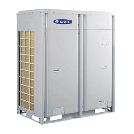
- Page 7 Gree Photovoltaic Direct-driven Inverter VRF System technology. According to change the displacement of compressor, stepless capacity regulation within range of 10%-100% can be realized. Gree air conditioner is absolutely your best choice. 2.1 Names of Main Parts Fig. 2.1.1 ①...
- Page 8 + GMV-Y120WM/C-F(U) (Combined) + GMV-Y120WM/C-F(U) 2.3 Combinations of Indoor and Outdoor Units Max number of Max number of ODU Model connectable IDU ODU Model connectable IDU (unit) (unit) GMV-Y72WM/C-F(U) GMV-Y240WM/C-F(U) GMV-Y96WM/C-F(U) GMV-Y264WM/C-F(U) GMV-Y120WM/C-F(U) GMV-Y288WM/C-F(U) GMV-Y144WM/C-F(U) GMV-Y312WM/C-F(U) GMV-Y168WM/C-F(U) GMV-Y336WM/C-F(U) GMV-Y360WM/C-F(U) GMV-Y192WM/C-F(U) GMV-Y216WM/C-F(U) The total capacity of indoor units should be within 50%~135% of that of outdoor units.
- Page 9 3 Preparation before Installation NOTICE! The picture is only used for reference and the actual product prevails. Unit: mm(in.). 3.1 Standard Parts Please use the following standard parts supplied by Gree. Parts for Outdoor Unit Number Name Picture...
- Page 10 Photovoltaic Direct-driven Inverter VRF Parts for Outdoor Unit Number Name Picture Quantity Remarks Photovoltaic Used with the photovoltaic connector negative pole terminal (negative pole) Photovoltaic Used with the photovoltaic positive pole connector (positive pole) terminal Photovoltaic Used with the photovoltaic negative pole connector (negative pole) terminal...
- Page 11 Photovoltaic Direct-driven Inverter VRF (5) Keep the indoor and outdoor units close to each other as much as possible so as to decrease the pipe length and bends. (6) Never allow children to approach to the unit and take measures to prevent childr en touching the unit. 3.2.1 When the outdoor unit is totally surrounded by walls, please refer to following figures for space dimension.
- Page 12 Photovoltaic Direct-driven Inverter VRF 3.2.1.3 Space dimension for three-module unit Unit: mm(in.) Fig.3.2.3 3.2.2 When there is wall (or similar obstruction) above the unit, keep the distance between the unit top and the wall at least 3000mm(118-1/8in.) or above. When the unit is located in a totally open space with no obstructions in four directions, keep the distance between the unit top and wall at least 1500mm(59in.) or above (See Fig.
- Page 13 Photovoltaic Direct-driven Inverter VRF Unit: mm(in.) Fig.3.2.4 Fig.3.2.5 3.2.3 Space dimension for multiple-module unit For keeping good ventilation, make sure there is no obstruction above the unit. When the unit is located at a half-open space (front and left/right side is open), install the unit as per the same or opposite direction.
- Page 14 Photovoltaic Direct-driven Inverter VRF 3.2.4 Considering the seasonal wind in outdoor unit installation Anti-monsoon installation requirement for unit not connecting exhaust duct Fig.3.2.8 Fig.3.2.9 Anti-monsoon installation requirement for unit connecting exhaust duct Fig.3.2.10...
- Page 15 Photovoltaic Direct-driven Inverter VRF 3.2.5 Considering snow in outdoor unit installation Fig.3.2.11 3.3 Piping Work Requirements There should be no fall among outdoor modules. Refer to the table below for piping work requirements. R410A Refrigerant System Outer Diameter mm (in.) Wall Thickness mm(in.) Type Φ6.35(1/4)
- Page 16 Photovoltaic Direct-driven Inverter VRF 4 Installation Instruction 4.1 Physical Dimension of the Outdoor Unit and Mounting Hole Outline and Physical Dimention of GMV-Y72WM/C-F(U). Unit: mm(in.) Fig.4.1.1...
- Page 17 Photovoltaic Direct-driven Inverter VRF Outline and Physical Dimention of GMV-Y96WM/C-F(U) and GMV-Y120WM/C-F(U). Unit: mm(in.) Fig.4.1.2...
- Page 18 Photovoltaic Direct-driven Inverter VRF 4.2 Connection Pipe 4.2.1 Schematic Diagram of Piping Connection Fig.4.2.1...
- Page 19 Photovoltaic Direct-driven Inverter VRF 4.2.2 Schematic Diagram of Piping Sequence GMV-Y72WM/C-F(U) Fig.4.2.2 GMV-Y96WM/C-F(U) and GMV-Y120WM/C-F(U). Fig.4.2.3...
- Page 20 Photovoltaic Direct-driven Inverter VRF 4.2.3 Allowable pipe length and drop height among indoor and outdoor units Y type branch joint is adopted to connect indoor and outdoor units. Connecting method is shown in the figure below. Remark: Equivalent length of one Y-type manifold is about 0.5m(1-3/4ft.). Unit: m(ft.) Fig.4.2.4 L10: Length from the first branch to the farthest IDU;...
- Page 21 Outdoor Model Gas pipe size mm(in.) Liquid pipe size mm(in.) GMV-Y72WM/C-F(U) No need to enlarge pipe size No need to enlarge pipe size Φ12.7(1/2) GMV-Y96WM/C-F(U) No need to enlarge pipe size Φ15.9(5/8)
- Page 22 Photovoltaic Direct-driven Inverter VRF (4) If the length between an IDU and its nearest branch is above 10m(32 -4/5ft.), then increase the size of the liquid pipe of IDU (only for the pipe size that is≤6.35mm(1/4in.). 4.2.4 Connection Pipe among Outdoor Modules Fig.4.2.5 Unit: m(ft.) Fig.4.2.6...
- Page 23 Pipe size of basic outdoor module is shown as follows: Pipe between ODU and the first branch of IDU Basic Module Gas Pipe mm(in.) Liquid Pipe m m(in.) Φ19.05(3/4) Φ9.52(3/8) GMV-Y72WM/C-F(U) Φ22.2(7/8) Φ9.52(3/8) GMV-Y96WM/C-F(U) Φ28.6(1-1/8) Φ12.7(1/2) GMV-Y120WM/C-F(U) 4.2.5.2 For multi-module unit, select appropriate manifold connected to outdoor module as per the pipe size of basic module.
- Page 24 Photovoltaic Direct-driven Inverter VRF Pipe between module and branch of ODU Basic Module Gas Pipe mm(in.) Liquid Pipe mm(in.) Φ19.05(3/4) Φ9.52(3/8) GMV-Y72WM/C-F(U) Φ22.2(7/8) Φ9.52(3/8) GMV-Y96WM/C-F(U) Φ28.6(1-1/8) Φ12.7(1/2) GMV-Y120WM/C-F(U) Select the branch of outdoor module Model Select the branch of outdoor module ML01/A 4.2.5.3 Fitting pipe between two manifolds from basic modules...
- Page 25 Fig.4.2.10 Pipe between ODU and the first branch of IDU Basic Module Gas Pipe mm(in.) Liquid Pipe mm(in.) Φ19.05(3/4) Φ9.52(3/8) GMV-Y72WM/C-F(U) Φ22.2(7/8) Φ9.52(3/8) GMV-Y96WM/C-F(U) Φ28.6(1-1/8) Φ12.7(1/2) GMV-Y120WM/C-F(U) For multiple modules, the piping from ODU to the first branch of IDU is base d on the total rated capacity of outdoor modules.
- Page 26 Photovoltaic Direct-driven Inverter VRF Total rated capacity of outdoor Pipe between ODU and the first branch of IDU modules (multi-modular system) Gas pipe size mm(in.) Liquid pipe size mm(in.) Φ28.6(1-1/8) Φ15.9(5/8) GMV-Y216WM/C-F(U) Ф34.9(1-3/8) Φ15.9(5/8) GMV-Y240WM/C-F(U) Ф34.9(1-3/8) Ф19.05(3/4) GMV-Y264WM/C-F(U) Ф34.9(1-3/8) Ф19.05(3/4) GMV-Y288WM/C-F(U) Ф34.9(1-3/8) Ф19.05(3/4)
- Page 27 Photovoltaic Direct-driven Inverter VRF Total capacity of downstream R410A Refrigerant System Model indoor unit(s) C (KBtu/h) C < 68 FQ01A/A 68 ≤ C ≤ 102 FQ01B/A Y-type Manifold 102 < C ≤ 239 FQ02/A 239 < C FQ03/A C ≤ 136 FQ14/H1 C ≤...
- Page 28 Photovoltaic Direct-driven Inverter VRF 4.2.5.7 Fitting pipe between indoor unit and manifold Manifold should be matched with fitting pipe of indoor unit. Fig.4.2.14 Pipe between indoor branch and IDU Rated capacity of indoor unit C(Btu/h) Gas Pipe mm(in.) Liquid Pipe mm(in.) C ≤...
- Page 29 Photovoltaic Direct-driven Inverter VRF Fig.4.3.1 1) Align the expansion end of copper pipe with the center of threaded joint. Tighten the flare nuts with your hands. 2) Tighten the flare nuts with torque wrench until you hear "click" sound. 3) Use sponge to wrap the connecting pipe and joints without thermal insu lation and tie it up with plastic tape.
- Page 30 Photovoltaic Direct-driven Inverter VRF (2) Manifold has serveral pipe sections with different pipe size, which facilitates to match with various copper pipe. Use pipe cutter to cut in the middle of the pipe section with different pipe size and deburr as well. See Fig. 4.3.3. Fig.
- Page 31 Photovoltaic Direct-driven Inverter VRF (19-11/16in.). The length of a straight pipe before the main pipe port of the manifold cannot be less than 500mm (19-11/16in.). The length of a straight pipe between the branch of the manifold and the IDU cannot be less than 500mm(19 -11/16in.). See Fig.4.3.5.
- Page 32 Photovoltaic Direct-driven Inverter VRF outlet pipes are horizontal at the lower side. See Fig.4.3.7. Fig.4.3.7 (5) Thermal insulation for pipeline 1) To avoid condensate or water leakage on connecting pipe, the gas pipe and liquid pipe must be wrapped with thermal insulating material and adhesive pipe for insulation from the air.
- Page 33 Photovoltaic Direct-driven Inverter VRF Fig.4.3.8 4) Manifold attached foam can not be taken as insulating material. 5) When wrapping the tape, the later circle should cover half of the former one. Don’t wrap the tape so tightly, otherwise the insulation effect will be weakened. 6) After wrapping the pipe, adopt sealing material to completely fill the hole so as to prevent wind and rain from entering the room.
- Page 34 Photovoltaic Direct-driven Inverter VRF Fig.4.4.1 Fig.4.4.2 4.4.2 Additional refrigerant charging Outdoor unit has been charged refrigerant before delivery. Charge additional refrigerant for field-installed connecting pipe. If the pipeline is longer than 1m(39-3/8in.), please refer to the following table for charging amount of refrigerant. (Liquid pipe prevails) How much additional refrigerant should be charged.
- Page 35 Photovoltaic Direct-driven Inverter VRF (1) IDU/ODU ra ted capacity collocation ra tio C = Sum of rated cooling capacity o f indoor unit / Sum of rated cooling capacity of outdoor unit. (2) If all of the indoor units are fresh air indoor units, the quantity o f refrigerant added to each module is 0kg. (3) If ou tdoor air processor is connected with normal VR F indoor uni t, adopt the perfusion method for normal indoor unit for perfusion.
- Page 36 Photovoltaic Direct-driven Inverter VRF 4.4.3 Precautions on Refrigerant Leakage (1)Personnel related to air conditioning engineering design and installation operators must abide by the safety requirement for preventing refrigerant leakage specified in local laws and regulations. (2)The units adopt the R410A refrigerant, which is nonflammable and nontoxic. However, the space for refrigerant leakage must be sufficient to ensure that the r efrigerant concentration does not exceed that specified in the safety requirement;...
- Page 37 Outdoor Unit (208V) Minimum Circuit Maximum Overcurrent Power Supply Fuse Capacity Ampacity Protection Outdoor units V/ Ph /Hz 208V 3~ 60Hz 35.3 GMV-Y72WM/C-F(U) 208V 3~ 60Hz 43.6 GMV-Y96WM/C-F(U) 208V 3~ 60Hz 44.8 GMV-Y120WM/C-F(U) 208V 3~ 60Hz 45+45 35.3+35.3 45+45 GMV-Y144WM/C-F(U)
- Page 38 Outdoor Unit (240V) Minimum Circuit Maximum Overcurrent Power Supply Fuse Capacity Ampacity Protection Outdoor units V/ Ph /Hz 240V 3~ 60Hz 30.3 GMV-Y72WM/C-F(U) 240V 3~ 60Hz 37.3 GMV-Y96WM/C-F(U) 240V 3~ 60Hz 39.8 GMV-Y120WM/C-F(U) 240V 3~ 60Hz 40+40 30.3+30.3 40+40 GMV-Y144WM/C-F(U)
- Page 39 Photovoltaic Direct-driven Inverter VRF 4.5.3 Connection of power cord (1) Before obtaining access to terminals, all supply circuits must be disconnected. (2) If units are type I electrical appliances, they must be reliably grounded. (3 Ground resistance must be in accord with requirements of local s tandard. (4) The green-yellow wire within units are ground wire.
- Page 40 Photovoltaic Direct-driven Inverter VRF Fig.4.5.2 4.6.2 Communication mode of GMV DC Inverter Units CAN bus mode is taken for communication between IDU and ODU and communication among IDUs. 4.6.3 Selection and connection model 4.6.3.1Select communication material NOTICE! If air conditioners are installed at places where there’s strong electromagnetic interference, the communication wire of IDU and wired controller must use shielded wire and the communication wire between IDU and IDU/ODU must use shielded twisted pair.
- Page 41 Photovoltaic Direct-driven Inverter VRF (1)Select communication wire between IDU and wired controller Total length of communication line Material type Wire size Remarks between IDU unit and wired controller L m(ft.) 1. Total length of communication line can't exceed 250m(820-1/5ft.). Light/Ordinary 2.
- Page 42 Photovoltaic Direct-driven Inverter VRF 4.6.3.2 Connection mode of communication (1) All communication wires of GMV5 must be connected in series rather than in star. Fig.4.6.3 Fig.4.6.4 Fig.4.6.5...
- Page 43 Do not simply twist the wires together. 4.6.4 Communication address Auto addressing technology is adopted for Gree Photovoltaic Direct-driven Inverter VRF System IDU and ODU. No need to set address codes manually. Only the addresses of master unit and central control are needed to be set (address of central control is only needed when there are multiple refrigeration systems).
- Page 44 Photovoltaic Direct-driven Inverter VRF 4.7 Connection Method and Steps for System Communication 4.7.1 Communication connection between IDU and ODU NOTICE! The centralized controller can be installed when it is necessary. Connect IDU and ODU via terminal D1/D2 of wiring board XT2. Below are the connection graphics of single unit and modular units: Fig.4.7.1 Connection of single unit...
- Page 45 Photovoltaic Direct-driven Inverter VRF Fig.4.7.2 Connection of modular unit (1) For modular outdoor units, if there are multiple outdoor modules, then the master unit must be the first outdoor module on the communication wire and should not connect with IDU (master unit is set b y SA8 o f the outdoor main board).
- Page 46 Photovoltaic Direct-driven Inverter VRF 4.7.2 Communication connection between IDU and wired controller There are 4 kinds of connection between IDU and wired controlle r, as shown below: Fig.4.7.3 One wired controller controls one IDU Fig.4.7.4 Two wired controllers controls one IDU Fig.4.7.5 One wired controller controls multiple IDUs...
- Page 47 Photovoltaic Direct-driven Inverter VRF Fig.4.7.6 Two wired controllers control multiple IDUs When two wired controllers control multiple IDUs, the wired controller can be connected to any one IDU, provided that the connected IDU is of the same series. Meanwhile, one and only one of the wired controllers must be set as a slave controller.
- Page 48 Photovoltaic Direct-driven Inverter VRF Fig.4.7.7...
- Page 49 Photovoltaic Direct-driven Inverter VRF 4.8 External Electrical Wiring Diagram (1) Every unit should be equipped with a circuit breaker for short-circuit and overload protection. In general, circuit breaker is at OFF status. (2) During operation, all indoor units and outdoor units belonging to the same system must be kept energi zed status.
- Page 50 Photovoltaic Direct-driven Inverter VRF 4.8.2 External wiring diagram of modular connection AC POWER 3 Power cord PV Array PV Array PV Array Power cord PV1+PV1- PV2+ PV2- PV3+PV3- PV4+PV4- PV1+PV1- PV2+ PV2- PV3+PV3- PV4+PV4- PV1+PV1- PV2+ PV2- PV3+PV3- PV4+PV4- DC POWER DC POWER DC POWER POWER...
- Page 51 Photovoltaic Direct-driven Inverter VRF (4) Any operation for this device must be done by relevant professionals; if maintenance of the system is needed, please contact related professionals; pay attention to the safety notice listed in all safety instructions and installation documents. (5)...
- Page 52 For detailed configuration procedur es, please refer to related instructions in the owner’s manual. ② Above configuration shall be done by the professional engineering personnel who is accredited by Gree. Customer shall not change the configuration; otherwise unit malfunction may be caused. 4.9.2 Installation project of photovoltaic system The system construction is as below.
- Page 53 Photovoltaic Direct-driven Inverter VRF before using. Common photovoltaic battery sub-assy is shown as below. Monocrystalline Multicrystal Thin film sub-assy Silicon sub-assy silicon sub-assy Fig.4.9.2 Place it carefully during transportation to avoid collision among photovoltaic sub-accessories and among photovoltaic sub-accessories and supports. The photovoltaic sub-accessories shall be placed on the keel and fixed by pressing.
- Page 54 Photovoltaic Direct-driven Inverter VRF requirement. Finally, adjust the overcurrent circuit breaker of cabinet, relays and mechanical linkage. 5 Check Items after Installation and Trial Run 5.1 Check Items after Installation Check Items Conditions Might Happen Check Has the unit been fixed firmly? The unit may drop, shake or emit noise.
- Page 55 Photovoltaic Direct-driven Inverter VRF transportation. (5) Check if the terminals of electrical element is loose and the phase sequence is correct or not. (6) Check the valve: For single-module unit, fully open the gas and liquid valve and close oil balance valve; For dual/three module unit, fully open the gas, liquid valve and oil balance valve.
- Page 56 Photovoltaic Direct-driven Inverter VRF Grid connection certification standard setting, grid parameter configuration and setting of residual power sending to the grid must be done before debugging or turning on the unit. ③If it is in the interface not for setting function, press SW3 function button to enter function setting interface and select related function configuration to modify configuration.
- Page 57 Photovoltaic Direct-driven Inverter VRF LED1 LED2 LED3 Function Display Voltage Display Current Display Code Mode selection Mode Status Mode Flicker After selecting corresponding voltage, press SW7 to confirm the selected mode. Meanwhile, LED3 display is flickering, which means entering frequency configuration. Corresponding display of all modules are as below: LED1 LED2...
- Page 58 Photovoltaic Direct-driven Inverter VRF (3) Setting of residual power sending to the grid After entering this function setting, default display of master unit is as below. Other basic modules will display according to normal operation mode: LED1 LED2 LED3 Function Display Current Display...
-
Page 59: Compressor
Photovoltaic Direct-driven Inverter VRF Description of each stage of debugging progress —— Debugging code Progress code Status code LED1 LED2 LED3 Meaning progress Display Display Display Code code Code status status status light light blink System is allocating addresses. Master IDU is not set. Please set master IDU. - Page 60 Photovoltaic Direct-driven Inverter VRF Description of each stage of debugging progress Debugging —— Progress code Status code code LED1 LED2 LED3 Meaning progress Display Display Display Code code Code status status status System refrigerant is not enough. light light light System downtime equilibrium pressure 09_Refrigerant is lower than 0.3MPa(4-2/5psig).
- Page 61 LED2 and LED3 display “OF”. 5.2.2.3 Debugging operation mode Gree Photovoltaic Direct-driven Inverter VRF System has two debugging modes: one is direct operation on main board of outdoor units while the other is PC operation via special software. In PC software debugging, indoor/outdoor parameters can be displayed and historical data can be recorded and inquired.
- Page 62 Photovoltaic Direct-driven Inverter VRF button on the master module for at least 5s to enable debugging; Step 6: Wait. Unit will then start progress 01 and 02; in progress 01, if master unit is not correctly set, progress 01 will show the following errors: Debugging Progress Code Status Code...
-
Page 63: Compressor
Photovoltaic Direct-driven Inverter VRF debugging again. Step 8: in progress 04, the quantity of IDUs needs to be confirmed manually. Main board of each module will display: Debugging code Progress code Status code LED1 LED2 LED3 Progress Display Display Display Code Code Code... - Page 64 Photovoltaic Direct-driven Inverter VRF If no error is detected, system will display as below and then start next progress. —— Debugging code Progress code Status code LED1 LED2 LED3 Meaning progress Display Display Display Code code Code status status status 06_Detect No error is detected in outdoor outdoor...
-
Page 65: Compressor
Photovoltaic Direct-driven Inverter VRF —— Debugging code Progress code Status code LED1 LED2 LED3 Meaning progress Display Display Display Code code Code status status status 08_Confirm Preheat time for compressor is 8h. preheated Light Light Light Start next progress. compressor If less than 8h of preheat time is detected, system will give error alarm and display as below. - Page 66 Photovoltaic Direct-driven Inverter VRF If unit detects that valve status is not normal, it will display as below: —— Debugging code Progress code Status code LED1 LED2 LED3 Meaning progress Display Display Display Code code Code status status status 10_Status judgments of Light Light...
- Page 67 Photovoltaic Direct-driven Inverter VRF according to ambient temperature. A If cooling mode is selected, relevant display is as below: —— Debugging code Progress code Status code LED1 LED2 LED3 Meaning progress Display Display Display Code code Code status status status Debugging is enabled in cooling mode Light Light...
- Page 68 Photovoltaic Direct-driven Inverter VRF —— Debugging code Progress code Status code LED1 LED2 LED3 Meaning progress Display Display Display Code code Code status status status Debugging is finished. System is on 17_Debugging standby condition. LED1 displays Light Light Light finished module address.
-
Page 69: Compressor 1
Photovoltaic Direct-driven Inverter VRF photovoltaic multi VRF Reference of Debug Parameters of System Debug item Parameter name Unit Reference Operating freq. of Varies from 20Hz to 95Hz inverter compressor 1 Current of inverter According to different operating freq. and different compressor 1 load, current will vary from 7A to 40A. - Page 70 Otherwise, there will be collision malfunction of the project codes. For detail operation methods, please refer to the Photovoltaic Multi VRF Installation and Maintenance Manual. (2) If problem cannot be solved a fter checking the abo ve items, please contact Gree service center and show phenomena and models.
- Page 71 Photovoltaic Direct-driven Inverter VRF Following circumstance are not malfunction. “Malfunction” Reason When unit is started immediately a fter it is just Overload protection switch makes it run turned off after 3 minutes delay Unit doesn’t run When power is turned on Standby operating for about 1 minute Mist comes from Under cooling...
-
Page 72: High Pressure Ratio Protection Of
Photovoltaic Direct-driven Inverter VRF 7 Error Indication Inquiry method of malfunction display: combine division number and content number to check the corresponding malfunction. Indoor: Error Code Content Error Code Content Malfunction of lower water Malfunction of IDU temperature sensor of water tank Malfunction of ambient temperature Protection of indoor fan sensor... -
Page 73: Table Of Contents
Photovoltaic Direct-driven Inverter VRF Error Code Content Error Code Content Over-current protection of Malfunction of casing top compressor 1 temperature sensor of compressor 1 Over-current protection of Malfunction of casing top compressor 2 temperature sensor of compressor 2 Over-current protection of Malfunction of exit tube temperature compressor 3 sensor of mode exchanger... - Page 74 Photovoltaic Direct-driven Inverter VRF Error Code Content Error Code Content Malfunction of charging loop of driven Drive IPM high temperature of compressor protection of fan Failure startup of inverter Desynchronizing protection of compressor inverter fan AC current protection of inverter Malfunction of drive storage chip of compressor inverter outdoor fan...
-
Page 75: Oil-Return
Photovoltaic Direct-driven Inverter VRF Error Code Content Error Code Content Alarm because valve is abnormal Emergency status of module Malfunction of pipeline for IDU Rated capacity is too high Malfunction of pipeline for ODU No main unit The matching ratio of rated capacity Setting of main IDU is succeeded for IDU and ODU is too low Emergency operation DIP switch... - Page 76 (4) In the event of rusting, use the anti-rust paint to stop spreading of rust. 8.5 Parts Replacement Purchase parts from Gree appointed service center or dealer if necessary. NOTICE! During airtight and leakage test, never mix oxygen, ethyne and other dangerous gas into refrigeration circuit.
- Page 77 Gree. Warranty should meet the following requirements: (1) First run of the unit should be operated by professional personnel from Gree appointed service center. (2) Only Gree manufactured accessories can be used on the machine.
Need help?
Do you have a question about the GMV-Y72WM/C-F and is the answer not in the manual?
Questions and answers