Gree GMV Series Owner's Manual
Dc inverter vrf
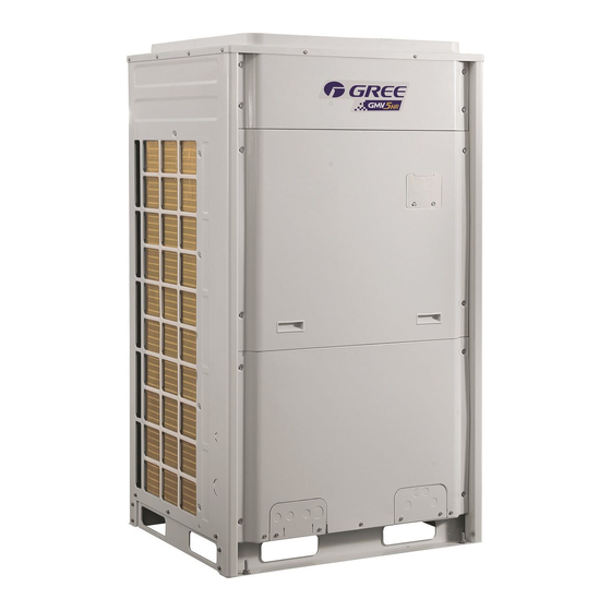
Hide thumbs
Also See for GMV Series:
- Service manual (368 pages) ,
- Owner's manual (73 pages) ,
- User manual (32 pages)

Related Manuals for Gree GMV Series


Summary of Contents for Gree GMV Series
- Page 1 Owner's Manual Original Instructions Commercial Air Conditioners GMV DC Inverter VRF Models: GMV-72WM/B-F (U) GMV-96WM/B-F (U) GMV-120WM/B-F (U) GMV-144WM/B1-F (U) …… GMV-360WM/B-F (U)
- Page 2 Preface Gree DC Inverter Multi VRF System, with the most advanced technologies in the world, uses eco-friendly refrigerant R410A as its cooling medium. For correct installation and operation, please read this manual carefully. This is the safety alert symbol. It is used to alert you to potential personal injury hazards.
-
Page 3: Table Of Contents
Contents 1 Safety Precautions ....................1 2 Product Introduction ..................... 2 2.1 Names of Main Parts ......................2 2.2 Combinations of Outdoor Units ................... 2 2.3 Combinations of Indoor and Outdoor Units ................3 2.4 The Range of Production Working Temperature..............4 3 Preparation before Installation ................ -
Page 4: Safety Precautions
(27) If anything abnormal happens (such as burning smell), please power off the unit and cut off the main power supply, and then immediately contact Gree appointed service center. If abnormality keeps going, the unit might be damaged and lead to electric shock or fire. -
Page 5: Product Introduction
GMV DC Inverter VRF 2 Product Introduction Gree Multi VRF Modular System adopts inverter compressor technology. According to change the displacement of compressor, stepless capacity regulation within range of 10%-100% can be realized. Various product lineup is provided with capacity range from 72kBtu/h to 360kBtu/h, which can be widely used in working area and especially applicable to the place with variable load change. -
Page 6: Combinations Of Indoor And Outdoor Units
GMV DC Inverter VRF 2.3 Combinations of Indoor and Outdoor Units Max number of Max number of ODU Model ODU Model connectable IDU (unit) connectable IDU (unit) GMV-72WM/B-F(U) GMV-216WM/B-F(U) GMV-96WM/B-F(U) GMV-240WM/B-F(U) GMV-120WM/B-F(U) GMV-264WM/B-F(U) GMV-144WM/B1-F(U) GMV-288WM/B-F(U) GMV-168WM/B1-F(U) GMV-312WM/B-F(U) GMV-144WM/B-F(U) GMV-336WM/B-F(U) GMV-168WM/B-F(U) GMV-360WM/B-F(U) GMV-192WM/B-F(U) The total capacity of indoor units should be within 50%~135% of that of outdoor units. -
Page 7: The Range Of Production Working Temperature
3 Preparation before Installation NOTICE! The picture is only used for reference and the actual product prevails. Unit: mm (in.). 3.1 Standard Parts Please use the following standard parts supplied by Gree. Parts for Outdoor Unit Number Name Picture... - Page 8 GMV DC Inverter VRF 3.2.1 When the outdoor unit is totally surrounded by walls, please refer to following figures for space dimension. 3.2.1.1 Space dimension for single-module unit Unit: mm (in.) Fig.3 3.2.1.2 Space dimension for dual-module unit Unit: mm (in.) Fig.4...
- Page 9 GMV DC Inverter VRF 3.2.1.3 Space dimension for three-module unit Unit: mm (in.) Fig.5 3.2.2 Space dimension for outdoor unit top When there is wall (or similar obstruction) above the unit, keep the distance between the unit top and the wall at least 3000mm (118-1/8in.) or above. When the unit is located in a totally open space with no obstructions in four directions, keep the distance between the unit top and wall at least 1500mm (59in.) or above (See Fig.6).
- Page 10 GMV DC Inverter VRF 3.2.3 Space dimension for multiple-module unit For keeping good ventilation, make sure there is no obstruction above the unit. When the unit is located at a half-open space (front and left/right side is open), install the unit as per the same or opposite direction.
- Page 11 GMV DC Inverter VRF Fig.11 Anti-monsoon installation requirement for unit connecting exhaust duct Fig.12 3.2.5 Considering snow in outdoor unit installation Fig.13...
-
Page 12: Piping Work Requirements
GMV DC Inverter VRF 3.3 Piping Work Requirements There should be no fall among outdoor modules. Refer to the table below for piping work requirements. R410A Refrigerant System Outer Diameter mm(in.) Wall Thickness mm(in.) Type Φ6.35(1/4) ≥0.8(1/32) Φ9.52(3/8) ≥0.8(1/32) Φ12.7(1/2) ≥0.8(1/32) Φ15.9(5/8) ≥1.0(3/76) -
Page 13: Physical Dimension Of The Outdoor Unit And Mounting Hole
GMV DC Inverter VRF 4.2 Physical Dimension of the Outdoor Unit and Mounting Hole Outline and Physical Dimensions of GMV-72WM/B-F (U). Unit: mm (in.) Fig.15... - Page 14 GMV DC Inverter VRF Outline and Physical Dimensions of GMV-96WM/B-F(U) 、GMV-120WM/B-F(U) and GMV-144WM/B1-F(U). Unit: mm (in.) Fig.16...
- Page 15 GMV DC Inverter VRF Outline and Physical Dimensions of GMV-168WM/B1-F(U). Unit: mm (in.) Fig.17...
-
Page 16: Connection Pipe
GMV DC Inverter VRF 4.3 Connection Pipe 4.3.1 Schematic Diagram of Piping Connection Fig.18... - Page 17 GMV DC Inverter VRF 4.3.2 Schematic Diagram of Piping Sequence GMV-72WM/B-F (U) Fig.19 GMV-96WM/B-F(U) / GMV-120WM/B-F(U) and GMV-144WM/B1-F(U) Fig.20 GMV-168WM/B1-F(U) Fig.21...
- Page 18 GMV DC Inverter VRF 4.3.3 Allowable pipe length and drop height among indoor and outdoor units Y type branch joint is adopted to connect indoor and outdoor units. Connecting method is shown in the figure below. Remark: Equivalent length of one Y-type manifold is about 0.5m (1-3/4ft.). Unit: m (ft.) Fig.22 L10: Length from the first branch to the farthest IDU;...
- Page 19 GMV DC Inverter VRF R410A Refrigerant System Allowable Value m(ft.) Fitting Pipe Difference between the pipe length from the first branch of IDU to the farthest IDU and the ≤40(131-1/4) L10-L11 pipe length from the first branch of IDU to the nearest IDU Equivalent length from the first branch to the ≤40(131-1/4)
- Page 20 GMV DC Inverter VRF Outdoor Model Gas pipe size mm(in.) Liquid pipe size mm(in.) Φ22.2(7/8) GMV-360WM/B-F(U) No need to enlarge pipe size (3) If the length between an IDU and its nearest branch is above 10m (32-4/5ft.), then increase the size of the liquid pipe of IDU (only for the pipe size that is≤6.35mm (1/4in.). 4.3.4 Connection Pipe among Outdoor Modules Fig.23 Unit: m (ft.)
- Page 21 GMV DC Inverter VRF 4.3.5 Fitting pipe between Outdoor Unit and the First Manifold 4.3.5.1 For single module system, pipe size (between outdoor unit and the first manifold) is determined by that of outdoor unit. Fig.25 Pipe size of basic outdoor module is shown as follows: Pipe between ODU and the first branch of IDU Basic Module Gas Pipe mm(in.)
- Page 22 GMV DC Inverter VRF Pipe between module and branch of ODU Basic Module Gas Pipe mm(in.) Liquid Pipe mm(in.) Φ19.05(3/4) Φ9.52(3/8) GMV-72WM/B-F(U) Φ22.2(7/8) Φ9.52(3/8) GMV-96WM/B-F(U) Φ28.6(1-1/8) Φ12.7(1/2) GMV-120WM/B-F(U) Φ28.6(1-1/8) Φ12.7(1/2) GMV-144WM/B1-F(U) Φ28.6(1-1/8) Φ15.9(5/8) GMV-168WM/B1-F(U) Select the branch of outdoor module Model Select the branch of outdoor module ML01/A...
- Page 23 GMV DC Inverter VRF 4.3.5.4 Fitting pipe between the first manifold from indoor unit and the end manifold from outdoor unit Single module unit Fig.28 Pipe between ODU and the first branch of IDU Basic Module Gas Pipe mm(in.) Liquid Pipe mm(in.) Φ19.05(3/4) Φ9.52(3/8) GMV-72WM/B-F(U)
- Page 24 GMV DC Inverter VRF Pipe between ODU and the first branch of IDU Total rated capacity of outdoor modules (multi-modular system) Gas pipe size mm(in.) Liquid pipe size mm(in.) Φ28.6(1-1/8) Φ12.7(1/2) GMV-144WM/B-F(U) Φ28.6(1-1/8) Φ15.9(5/8) GMV-168WM/B-F(U) Φ28.6(1-1/8) Φ15.9(5/8) GMV-192WM/B-F(U) Φ28.6(1-1/8) Φ15.9(5/8) GMV-216WM/B-F(U) Ф34.9(1-3/8) Φ15.9(5/8)
- Page 25 GMV DC Inverter VRF Total capacity of downstream R410A Refrigerant System Model indoor unit(s) C (KBtu/h) C<68 FQ01A/A 68≤C≤102 FQ01B/A Y-type Manifold 102<C≤239 FQ02/A 239<C FQ03/A C≤136 FQ14/H1 C≤232 T- type Manifold FQ18/H1 232<C FQ18/H2 4.3.5.6 Fitting pipe between manifolds Pipe size (between two manifolds at indoor unit side) is based on the total capacity of upstream indoor unit(s).
-
Page 26: Installation Of The Connection Pipe
GMV DC Inverter VRF 4.3.5.7 Fitting pipe between indoor unit and manifold Manifold should be matched with fitting pipe of indoor unit. Fig.32 Pipe between indoor branch and IDU Rated capacity of indoor unit C(Btu/h) Gas Pipe mm(in.) Liquid Pipe mm(in.) C≤9500 Φ9.52(3/8) Φ6.35(1/4) - Page 27 GMV DC Inverter VRF (4) Please use a torque wrench to connect union nut on the indoor unit. See Fig.33. Fig.33 1) Align the expansion end of copper pipe with the center of threaded joint. Tighten the flare nuts with your hands. 2) Tighten the flare nuts with torque wrench until you hear "click"...
- Page 28 GMV DC Inverter VRF (2) Manifold has several pipe sections with different pipe size, which facilitates to match with various copper pipe. Use pipe cutter to cut in the middle of the pipe section with different pipe size and deburr as well. See Fig. 35. Fig.
- Page 29 GMV DC Inverter VRF (2) Manifolds can be laid in the following ways: The length of a straight pipe between two manifolds cannot be less than 500 mm (19-11/16in.). The length of a straight pipe before the main pipe port of the manifold cannot be less than 500mm (19-11/16in.).
- Page 30 GMV DC Inverter VRF (4) Suspend the header to the ceiling, and be sure to install the T-type manifold so that the outlet pipes are horizontal at the lower side. See Fig.39. Fig.39 (5) Thermal insulation for pipeline. 1) To avoid condensate or water leakage on connecting pipe, the gas pipe and liquid pipe must be wrapped with thermal insulating material and adhesive pipe for insulation from the air.
-
Page 31: Air Purging And Refrigerant Charge
GMV DC Inverter VRF 3) Joints at indoor and outdoor units should be wrapped with insulating material and leave no clearance between pipe and wall. See Fig.40. Fig.40 1) Manifold attached foam can not be taken as insulating material. 2) When wrapping the tape, the later circle should cover half of the former one. Don’t wrap the tape so tightly, otherwise the insulation effect will be weakened. -
Page 32: Additional Refrigerant Charging
GMV DC Inverter VRF 4.5.2 Additional refrigerant charging Outdoor unit has been charged refrigerant before delivery. Charge additional refrigerant for field-installed connecting pipe. If the pipeline is longer than 1m (39-3/8in.), please refer to the following table for charging amount of refrigerant (Liquid pipe prevails). - Page 33 GMV DC Inverter VRF included IDUs is more than 4 sets. Please refer to the above table. Refrigerant charging amount B for 72kBtu/h module is 4.0kg (8.8pounds). Refrigerant charging amount B for 120 kBtu/h module is 4.0kg (8.8pounds). Refrigerant charging amount B for 120 kBtu/h module is 4.0kg (8.8pounds). So, Σ...
-
Page 34: Electric Wiring
GMV DC Inverter VRF Total amount of refrigerant (kg) in the system ≤The maximum amount of refrigerant (kg) in the system. (3) When the total amount of refrigerant in the system is more than the maximum amount of refrigerant, the cooling system should be designed again. In this case, the cooling system can also be separated into several cooling systems with small capacity, or add corresponding ventilation measures or alarming display. - Page 35 GMV DC Inverter VRF 4.6.2 Wiring of power cord Every unit should have corresponding short-circuit and overload protection. And also a main switch is required to control power supply or disconnection. See Fig.41. Fig.43 Outdoor Unit Minimum Circuit Maximum Overcurrent Power Supply Fuse Capacity Ampacity...
-
Page 36: System Communication
GMV DC Inverter VRF (4) The above sectional area is suitable for a maximum distance of 15m (49-1/5in.). If it’s over 15m (49-1/5in.), sectional area must be expanded to prevent overload current from burning the wire or causing fire hazard. (5) Specification of circuit breaker is based on the working condition where the ambient temperature of circuit breaker is 40℃(104℉). - Page 37 GMV DC Inverter VRF Fig.44 4.7.2 Communication mode of GMV DC Inverter Units CAN bus mode is taken for communication between IDU and ODU and communication among IDUs. 4.7.3 Selection and connection mode of GMV5 communication material 4.7.3.1 Select communication material NOTICE! If air conditioners are installed at places where there’s strong electromagnetic interference, the communication wire of IDU and wired controller must use shielded wire and the communication wire between IDU and IDU/ODU must use shielded twisted pair.
- Page 38 GMV DC Inverter VRF (1) Select communication wire between IDU and wired controller Total length of communication line Material type Wire size Remarks between IDU unit and wired controller L m(ft.) 1. Total length of communication line can't exceed 250m (820-1/5ft.). Light/Ordinary 2.
- Page 39 GMV DC Inverter VRF 4.7.3.2 Connection mode of communication (1) All communication wires of GMV5 must be connected in series rather than in star. Fig.47 Fig.48 Fig.49...
- Page 40 GMV DC Inverter VRF (2) All communication wires of GMV5 are connected by screws. Fig.50 (3) If a single communication wire is not long enough and needs to be connected, the connected joint must be welded or pressure-welded. Do not simply twist the wires together.
-
Page 41: Connection Method And Steps For System Communication
GMV DC Inverter VRF 4.8 Connection Method and Steps for System Communication 4.8.1 Communication connection between IDU and ODU NOTICE! The centralized controller can be installed when it is necessary. Connect IDU and ODU via terminal D1/D2 of wiring board XT2. Below are the connection graphics of single unit and modular units: Fig.51 Connection of single unit Fig.52 Connection of modular unit... - Page 42 GMV DC Inverter VRF (1) For modular outdoor units, if there are multiple outdoor modules, then the master unit must be the first outdoor module on the communication wire and should not connect with IDU (master unit is set by SA8 of the outdoor main board).
- Page 43 GMV DC Inverter VRF Fig.56 Two wired controllers control multiple IDUs When two wired controllers control multiple IDUs, the wired controller can be connected to any one IDU, provided that the connected IDU is of the same series. Meanwhile, one and only one of the wired controllers must be set as a slave controller.
- Page 44 GMV DC Inverter VRF Fig.57 (1) Wired controller and light board remote receiver can be used at the same time. (2) When light board remote receiver is used, please use remote controller at the same time.
- Page 45 GMV DC Inverter VRF 4.8.4 Communication connection of central controlling units NOTICE! The centralized controller can be installed when it is necessary. Port connection G1 and G2 on the wiring board XT2 of master unit among each multi VRF system (see below). Fig.58...
-
Page 46: External Electrical Wiring Diagram
GMV DC Inverter VRF 4.9 External Electrical Wiring Diagram (1) Every unit should be equipped with a circuit breaker for short-circuit and overload protection. In general, circuit breaker is at OFF status. (2) During operation, all indoor units and outdoor units belonging to the same system must be kept energized status. - Page 47 GMV DC Inverter VRF 4.9.2 External wiring diagram of modular connection Fig.60 NOTICE! Maximum number of ODU (N) and maximum number of IDU (n) are based upon the combination type of ODU. For details, please refer to the introduction of units’ combination.
-
Page 48: Check Items After Installation And Trial Run
GMV DC Inverter VRF 5 Check Items after Installation and Trial Run 5.1 Check Items after Installation Check Items Conditions Might Happen Check Has the unit been fixed firmly? The unit may drop, shake or emit noise. It may cause insufficient cooling/heating Have you done the gas leakage test? capacity. - Page 49 GMV DC Inverter VRF not. (6) Check the valve: For single-module unit, fully open the gas and liquid valve and close oil balance valve; for dual/three module unit, fully open the gas, liquid valve and oil balance valve. 5.2.2 Trial run 5.2.2.1 Notices (1) Before test operation, make sure unit is power on and compressor has been preheated for more than 8 hours.
- Page 50 GMV DC Inverter VRF (5) Before debugging, make sure the needed amount of refrigerant has been added to the pipe or at least 70% of the needed refrigerant has been added. (6) Description of each stage of debugging progress: Description of each stage of debugging progress ——...
- Page 51 GMV DC Inverter VRF Description of each stage of debugging progress —— Debugging code Progress code Status code LED1 LED2 LED3 Meaning progress Display Display Display Code code Code status status status System detects error in indoor components. XXXX is the project no. of XXXX the faulted IDU.
- Page 52 GMV DC Inverter VRF Description of each stage of debugging progress —— Debugging code Progress code Status code LED1 LED2 LED3 Meaning progress Display Display Display Code code Code status status status Debugging is enabled in heating mode light light light (debugging mode, auto-selected by system).
- Page 53 GMV DC Inverter VRF Debugging Progress Code Status Code Code LED1 LED2 LED3 Meaning Progress Display Display Display Code Code Code status status status System doesn’t have master unit. Reset light light light master unit. 01_01 Set More than 2 master units are set. Reset up master light light...
- Page 54 GMV DC Inverter VRF If the quantity displayed is the same with actual quantity, then press SW7 confirmation button on the master unit to confirm it. Unit will start next progress: Debugging code Progress code Status code LED1 LED2 LED3 Progress Code Display status...
- Page 55 GMV DC Inverter VRF —— Debugging code Progress code Status code LED1 LED2 LED3 Meaning progress Code Display status code Display status Code Display status 06_Detect Error System detects error in outdoor outdoor Light Light Light code components. components Elimination methods of above error can be found in Troubleshooting. Step11: progress 07 is “Detect indoor components”;...
- Page 56 GMV DC Inverter VRF Step 13: progress 09 is “Refrigerant judgments before startup”; If the refrigerant quantity inside the system meets the requirement of operation startup, system will display as below and start next progress. —— Debugging code Progress code Status code LED1 LED2...
- Page 57 GMV DC Inverter VRF Step 15: progress 11 is “Calculate refrigerant quantity manually”; No need to operate. System will start next progress. Step 16: progress 12 is “Confirm debugging startup”; In order to make sure all preparation work is done before startup, this step is designed for user to confirm the startup again.
- Page 58 GMV DC Inverter VRF —— Debugging code Progress code Status code LED1 LED2 LED3 Meaning progress Code Display status code Display status Code Display status Debugging is enabled in heating mode Light Light Light (debugging mode, auto-selected by system). Error Error occurs during debugging in heating Light Light...
- Page 59 GMV DC Inverter VRF 5.2.3 Appendix: judgment reference of normal operational parameters Reference of Debug Parameters of GMV5 DC Inverter Multi VRF System Debug item Parameter name Unit Reference Outdoor ambient ℃(° F) —— temp Discharge tube ℃(° F) When system compressor starts up, temp of discharge temp of inverter tube or casing top in cooling mode is within 70~95℃...
- Page 60 GMV DC Inverter VRF Reference of Debug Parameters of GMV5 DC Inverter Multi VRF System Debug item Parameter name Unit Reference voltage after rectification is: 220V X 1.414=311V. It’s driven bus voltage normal if actual voltage varies 15v from the calculated voltage.
-
Page 61: Common Malfunction And Troubleshooting
Otherwise, there will be collision malfunction of the project codes. For detail operation methods, please refer to the GMV5 Installation and Maintenance Manual. (2) If problem cannot be solved after checking the above items, please contact Gree service center and show phenomena and models. - Page 62 GMV DC Inverter VRF Following circumstance are not malfunction. “Malfunction” Reason When unit is started immediately after it is Overload protection switch makes it run after 3 just turned off minutes delay Unit doesn’t run When power is turned on Standby operating for about 1 minute Mist comes from Under cooling...
-
Page 63: Error Indication
GMV DC Inverter VRF 7 Error Indication Inquiry method of malfunction display: combine division number and content number to check the corresponding malfunction. Indoor: Error Code Content Error Code Content Malfunction of lower water temperature Malfunction of IDU sensor of water tank Malfunction of ambient temperature Protection of indoor fan sensor... - Page 64 GMV DC Inverter VRF Outdoor: Error Code Content Error Code Content Current sensor of compressor 2 is Malfunction of ODU abnormal Current sensor of compressor 3 is High-pressure protection abnormal Current sensor of compressor 4 is Discharge low-temperature protection abnormal Current sensor of compressor 5 is Low-pressure protection abnormal...
- Page 65 GMV DC Inverter VRF Error Code Content Error Code Content Drive IPM module protection of Malfunction of temperature sensor of oil compressor return 4 Malfunction of drive temperature sensor Malfunction of driving board of fan of compressor Drive IPM high temperature protection Driving board of fan operates abnormally of compressor Desynchronizing protection of inverter...
- Page 66 GMV DC Inverter VRF Debugging: Error Code Content Error Code Content Preheat time of compressor is Alarm because ODU quantity is insufficient inconsistent Wrong setting of ODU’s capacity Abnormal communication of converter code/jumper cap Power supply phase sequence Emergency status of compressor protection Refrigerant-lacking protection Emergency status of fan...
-
Page 67: Maintenance And Care
GMV DC Inverter VRF Status: Error Code Content Error Code Content Unit waiting for debugging Shielding status Refrigerant recovery operation of SE operation setting of system after-sales Defrosting Compulsory defrosting Limit setting for max. capacity/output Oil-return capacity Compulsory excursion of engineering Heat pump function setting code of IDU Quiet mode setting... -
Page 68: Notice Before Seasonal Use
Gree. Warranty should meet the following requirements: (1) First run of the unit should be operated by professional personnel from Gree appointed service center. (2) Only Gree manufactured accessories can be used on the machine.
Need help?
Do you have a question about the GMV Series and is the answer not in the manual?
Questions and answers