
Related Manuals for IEI Technology ICPMB-8660


Summary of Contents for IEI Technology ICPMB-8660
- Page 1 ICPMB-8660 SOCKET 478 PENTIUM 4 Motherboard with SATA & Ethernet & USB 2.0 User Manual Version 1.0 July 21, 2004 ©Copyright 2004 by ICP Electronics Inc. All Rights Reserved.
- Page 2 Trademarks ICPMB-8660 is registered trademarks of ICP Electronics Inc.; IBM PC is a registered trademark of International Business Machines Corporation. INTEL is a registered trademark of INTEL Corporation. Award is registered trademarks of American Megatrends Inc., Other product...
-
Page 3: Table Of Contents
Introduction ..............1 Specifications ................2 What You Have................4 Installation ..............5 ICPMB-8660’s Layout ..............6 ICPMB-8660’s Dimensions (Unit : mm) ........7 Unpacking Precautions............... 8 COM2 RS232/RS422/485 Selection ........9 Clear CMOS Setup..............9 Compact Flash Master/Slave Function Setting....... 9 Connection.............. - Page 4 Fan Connector ................16 3.10 Serial ATA Connector ............... 17 3.11 VGA Connectors................ 17 3.12 LAN Connector ................. 18 3.13 Audio Connectors ..............18 3.14 LAN LED Connector..............19 3.15 External Switches and Indicators ..........19 3.16 ATX +12V Power connector............. 20 3.17 RS422/485 connector ...............
- Page 5 4.10 PnP/PCI Configuration Setup ............ 40 4.11 PC Health Status ................. 42 4.12 Frequency/Voltage Control ............42 4.13 Load Fail-Safe Defaults .............. 43 4.14 Load Optimized Defaults ............43 4.15 Set Password ................43 4.16 Exit Selecting................44 Appendix A. Watchdog Timer ........ 45 Appendix B.
-
Page 6: Introduction
The integrated graphics controller provides 3D, 2D, and display capabilities. ICPMB-8660 is supports one or two 64-bit wide DDR data channels. Available bandwidth up to 2.7GB/s for single-channel mode and 5.4GB/s in dual-channel mode. For the application that needs high speed serial transmission, the ICPMB-8660 provides USB2.0 for your choice. -
Page 7: Specifications
1.1 Specifications Intel Pentium 4 Processor, supports 400/533/800 CPU(PGA 478) MHz PSB (set by BIOS) Bus interface AGP/PCI bus PCI: 33MHz Bus speed DMA channels Interrupt levels Chipset INTEL 865G / ICH5 Two 184-pin DIMM sockets support DDR333/400 RAM memory SDRAM .Support one or two 64-bit wide DDR data channels. - Page 8 Supports two independent serial ATA Serial ATA channels. Data transfer rate is up to 150MB/s PCI interface. INTEL 82540EM or Realtek RTL8110S Gigabit Ethernet controller. Ethernet Supports full 10,100 and1000-bast-T Ethernet Keyboard and PS/2 A connector is located on the mounting bracket for easy connection to a keyboard or PS/2 mouse.
-
Page 9: What You Have
1.2 What You Have In addition to this User's Manual, the ICPMB-8660 package includes the following items: • ICPMB-8660 Single Board Computer X1. • RS-232 Cable with bracket X1. • FDD cable X1. • IDE cable X2. • SATA cable X2. -
Page 10: Installation
Installation This chapter describes how to install the ICPMB-8660. First a layout diagram of the ICPMB-8660 is shown, followed by unpacking information that should be carefully followed. The jumpers and switch settings for the ICPMB-8660 configuration, such as CPU type selection, system clock setting, and... -
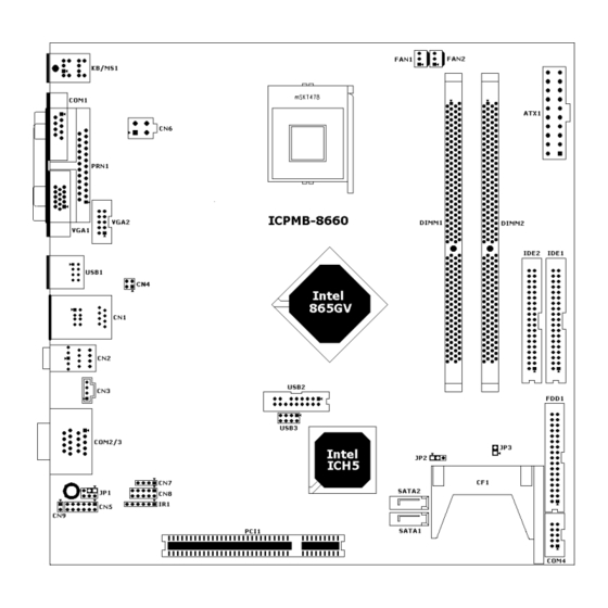
Page 11: Icpmb-8660'S Layout
ICPMB-8660’s Layout... -
Page 12: Icpmb-8660'S Dimensions (Unit : Mm)
ICPMB-8660’s Dimensions (Unit : mm) -
Page 13: Unpacking Precautions
Ground yourself to remove any static charge before touching your ICPMB-8660. You can do it by using a grounded wrist strap at all times or by frequently touching any conducting materials that is connected to the ground. -
Page 14: Com2 Rs232/Rs422/485 Selection
COM2 RS232/RS422/485 Selection • JP1: COM2 RS232/RS422/485 Selection Description 1-3 Short RS232 (default)* 3-5Short RS422 2-4 Short 3-5 Short RS485 4-6 Short Note: When RS422/485 is in use, the COM2’s RS232 port will be disabled. Clear CMOS Setup To clear the CMOS Setup (e.g. you have forgotten the password, you must clear the CMOS to reset the password), you have to close the JP2 (2-3) for about 3 seconds, then open it. -
Page 15: Connection
Connection This chapter describes how to connect peripherals, switches and indicators to the ICPMB-8660 board. Label Function IDE1 & IDE2 Ultra ATA100 Primary & Secondary IDE connectors FDD1 Floppy connector PRN1 Parallel port connector COM1,2,3,4 Serial port connectors Compact Flash Storage Card Type II connector... -
Page 16: Pci E-Ide Disk Drive Connectors
CHRDY REV. PULL LOW DACK GROUND-DEFAULT INTERRUPT HDC CS0# HDC CS1# HDD ACTIVE# GROUND Floppy Connector The ICPMB-8660 board is equipped with a 34-pin daisy-chain drive connector cable. • FDD1 : Floppy Connector DESCRIPTION DESCRIPTION GROUND RWC0- GROUND GROUND RWC1-... -
Page 17: Parallel Port Connector
GROUND INDEX- GROUND MO-A GROUND DS-B GROUND DS-A GROUND MO-B GROUND DIR- GROUND STEP- GROUND GROUND WGATE- GROUND TRK0- GROUND GROUND RDATA- GROUND HEAD- GROUND DSKCHG- Parallel Port Connector Usually, a printer is connected to the parallel port. The ICPMB- 8660 includes an on-board parallel port •... -
Page 18: Serial Port
Serial Port The ICPMB-8660 offers Four high speed NS16C550 compatible UART’s with 16-byte Read/Receive FIFO serial ports. • COM1: D-SUB Serial Port Connector DESCRIPTION DESCRIPTION (DCD3) (DSR1) (RXD3) (RTS1) (TXD3) (CTS1) (DTR3) (RI1) GROUND • COM2/3 : D-SUB Serial Port Connector... -
Page 19: Compact Flash Storage Card Socket
Compact Flash Storage Card Socket The ICPMB-8660 configures Compact Flash Storage Card in IDE Mode. This type II Socket is compatible with IBM Micro Drive. • CF1 : Compact Flash Storage Card Socket pin assignment PIN NO. DESCRIPTION PIN NO. -
Page 20: Irda Infrared Interface Port
IrDA Infrared Interface Port The ICPMB-8660 comes with an integrated IrDA port which supports either a Serial Infrared(SIR) or an Amplitude Shift Keyed IR(ASKIR) interface. • IR1: IrDA connector DESCRIPTION IR-RX Ground IR-TX CIRRX USB Port Connector The ICPMB-8660 is equipped with Eight USB(Version. 2.0) ports for the future new I/O bus expansion. -
Page 21: Keyboard/Mouse Connector
KB CLOCK MS CLOCK Fan Connector The ICPMB-8660 also has a CPU with cooling fan connector and chassis fan connector, which can supply 12V/500mA to the cooling fan. There is a “rotation” pin in the fan connector, which transfers the fan’s rotation signal to the system BIOS in order... -
Page 22: Serial Ata Connector
• FAN1,FAN2 : CPU Fan Connector DESCRIPTION Ground +12V Rotation Signal 3.10 Serial ATA Connector The ICPMB-8660 provide 2 Serial ATA ports to connect with Serial ATA devices. • SATA1, SATA2 : Serial ATA Connector PIN NO. DESCRIPTION DESCRIPTION S_TXP... -
Page 23: Lan Connector
HSYNC GROUND VSYNC GROUND 3.12 LAN Connector The ICPMB-8660 is equipped with Ethernet Controllers 10/100Mbps, which are connected to the LAN via an RJ45 LAN connector. The pin assignments are as follows: • CN1 : RJ45 Connector (10/100/1000) PIN DESCRIPTION... -
Page 24: Lan Led Connector
3.14 LAN LED Connector • CN4 : LAN LED Connector PIN DESCRIPTION DESCRIPTION ACT_LED- ACT_LED+ LINK_LED- LINK_LED+ 3.15 External Switches and Indicators There are several external switches and indicators for monitoring and controlling your CPU board. All functions are in the CN5connector. -
Page 25: Atx +12V Power Connector
This kind of response is highly needed for harsh and critical industrial operating environment. That’s why we design 4-bit digital inputs and 4-bit digital outputs on the ICPMB-8660 Digital Input and Output are control signals generally. You can use these signals to control external devices that needs On/Off circuit or TTL devices. -
Page 26: Ibutton Connector
• CN8: Digital I/O connector PIN DESCRIPTION DESCRIPTION GROUND GPO3 GPO2 GPO1 GPO0 GPI3 GPI2 GPI1 GPI0 3.19 iButton connector • CN9: iButton connector PIN DESCRIPTION DESCRIPTION iButton IN/OUT GROUND 3.20 ATX Power connector • ATX1: ATX Power connector DESCRIPTION PIN DESCRIPTION VCC3 VCC3 VCC3... -
Page 27: Award Bios Setup
Award BIOS Setup 4.1 Introduction This chapter discusses the Setup program written in the BIOS. It will give you a step-by-step guidance to configure your system. The user- defined configuration is then stored in battery-backed CMOS RAM, which retains the customized information while the power is off. 4.2 Starting Setup The BIOS is immediately active when you turn on the computer. -
Page 28: Using Setup
4.3 Using Setup In general, you can use the arrow keys to highlight items, press <Enter> to select, use the PageUp and PageDown keys to change entries, press <F1> for help and press <Esc> to quit. The following table provides more details about how to navigate in the Setup program using the keyboard. - Page 29 Note that a brief description of each highlighted selection appears at the bottom of the screen. 4.4.1 Setup Items The main menu includes the following main setup categories. Recall that some systems may not include all entries. Standard CMOS Features Use this menu for basic system configuration.
- Page 30 Power Management Setup Use this menu to configure your settings for power management. See section 4.9 for the details. PnP / PCI Configuration This entry appears if your system supports PnP / PCI. See section 4.10 for the details. PC Health Status Use this menu to monitor your hardware.
-
Page 31: Standard Cmos Setup
Exit Without Save Abandon all CMOS value changes and exit setup. See section 4.15 for the details. 4.5 Standard CMOS Setup The items in Standard CMOS Setup Menu are divided into 10 categories. Each category includes no, one or more than one setup items. - Page 32 Drive A None Select the type of floppy Drive B 360K, 5.25 in disk drive installed in your 1.2M, 5.25 in system 720K, 3.5 in 1.44M, 3.5 in 2.88M, 3.5 in Video EGA/VGA Select the default video CGA 40 device CGA 80 MONO Halt On...
-
Page 33: Advanced Bios Features
disk checking program. Access Mode Choose the access mode for this hard disk Large Auto 4.6 Advanced BIOS Features This section allows you to configure your system for basic operation. You have the opportunity to select the system’s default speed, boot-up sequence, keyboard operation, shadowing and security. - Page 34 Hard Disk Boot Priority This setting is to select hard disk boot priority CPU L1 & L2 Cache These two categories speed up memory access. However, it depends on CPU/chipset design. Enabled Enable cache Disabled Disable cache Hyper-Threading Technology This setting is to enable or disable hyper threading CPU support Quick Power On Self Test This category speeds up Power On Self Test (POST) after you power...
- Page 35 Seeks disk drives during boot up. Disabling speeds boot up. The choice: Enabled/Disabled. Boot Up NumLock Status Select power on state for NumLock. The choice: On/Off. Gate A20 Option Select if chipset or keyboard controller should control GateA20. Normal A pin in the keyboard controller controls GateA20 Fast Lets chipset control GateA20...
-
Page 36: Advanced Chipset Features
Select whether the password is required every time the system boots or only when you enter setup. System The system will not boot and access to Setup will be denied if the correct password is not entered at the prompt. Setup The system will boot, but access to Setup will be denied if the correct password is not entered at the prompt. - Page 37 This section allows you to configure the system based on the specific features of the installed chipset. This chipset manages bus speeds and access to system memory resources, such as DRAM and the external cache. It also coordinates communications between the conventional ISA bus and the PCI bus.
- Page 38 The Choice: 2, 3. DRAM Frequency For This field displays the capability of the memory modules that you are using either H/W TRAP. The choice: Auto, DDR266, DDR333, DDR400. System BIOS Cacheable Selecting Enabled allows caching of the system BIOS ROM at F0000h- FFFFFh, resulting in better system performance.
-
Page 39: Integrated Peripherals
4.8 Integrated Peripherals... - Page 40 On-Chip Primary/Secondary PCI IDE The integrated peripheral controller contains an IDE interface with support for two IDE channels. Select Enabled to activate each channel separately. The choice: Enabled, Disabled. IDE Primary/Secondary Master/Slave PIO...
- Page 41 The four IDE PIO (Programmed Input/Output) fields let you set a PIO mode (0-4) for each of the four IDE devices that the onboard IDE interface supports. Modes 0 through 4 provide successively increased performance. In Auto mode, the system automatically determines the best mode for each device.
- Page 42 The Choice: Enabled, Disabled. AC97 Audio This item allows you to decide to enable/disable the ALC202A chipset The choice: Auto, Disabled. Onboard FDC Controller Select Enabled if your system has a floppy disk controller (FDC) installed on the system board and you wish to use it. If you install and- in FDC or the system has no floppy drive, select Disabled in this field.
-
Page 43: Power Management Setup
The choice: SPP, EPP, ECP,ECP+EPP Watchdog Timer Unit Select Select the WatchDog Timer unit. The choice: Second, Minute 4.9 Power Management Setup The Power Management Setup allows you to configure you system to most effectively save energy while operating in a manner consistent with your own style of computer use. - Page 44 Power Management This category allows you to select the type (or degree) of power saving and is directly related to the following modes: Min. Power Saving Minimum power management. Doze Mode = 1 hr. Standby Mode = 1 hr., Suspend Mode = 1 hr., and HDD Power Down = 15 min.
-
Page 45: Pnp/Pci Configuration Setup
The choice: 1Min, 2Min, 4Min, 8Min, 12Min, 20Min, 30Min, 40Min, 1Hour, Disabled. HDD Power Down When enabled and after the set time of system inactivity, the hard disk drive will be powered down while all other devices remain active. The choice: 1Min, 2Min, 3Min, 4Min, 5Min, 6Min, 7Min, 8Min, 9Min, 10Min, Disabled. - Page 46 Reset Configuration Data Normally, you leave this field Disabled. Select Enabled to reset Extended System Configuration Data (ESCD) when you exit Setup if you have installed a new add-on and the system reconfiguration has caused such a serious conflict that the operating system can not boot. The choice: Enabled, Disabled .
-
Page 47: Pc Health Status
4.11 PC Health Status Note: normal CPU Fan RPM is over than 5000 RPM. If your CPU Fan RPM is less than that figure, something is wrong and the CPU will be in overheat condition. Make sure that the connection at Fan1/Fan2 is correct. -
Page 48: Load Fail-Safe Defaults
The choice: Enabled, Disabled. Spread Spectrum This item allows you to enable/disable the spread spectrum modulate. The choice: Enabled, Disabled. 4.13 Load Fail-Safe Defaults When you press <Enter> on this item you get a confirmation dialog box with a message similar to: Load Fail-Safe Defaults (Y/N) ? N Pressing ‘Y’... -
Page 49: Exit Selecting
To disable a password, just press <Enter> when you are prompted to enter the password. A message will confirm the password will be disabled. Once the password is disabled, the system will boot and you can enter Setup freely. PASSWORD DISABLED: When a password has been enabled, you will be prompted to enter it every time you try to enter Setup. -
Page 50: Appendix A. Watchdog Timer
Appendix A. Watchdog Timer The Watchdog Timer is provided to ensure that standalone systems can always recover from catastrophic conditions that cause the CPU to crash. This condition may have occurred by external EMI or a software bug. When the CPU stops working correctly, hardware on the board will either perform a hardware reset (cold boot) or a Non-Maskable Interrupt (NMI) to bring the system back to a known state. - Page 51 Example program: ; INITIAL TIMER PERIOD COUNTER W_LOOP: AX, 6F02H ;setting the time-out value BL, 30 ;time-out value is 48 seconds ; ADD YOUR APPLICATION PROGRAM HERE EXIT_AP, 1 ;is your application over? W_LOOP ;No, restart your application AX, 6F02H ;disable Watchdog Timer BL, 0 ;...
-
Page 52: Appendix B. Address Mapping
Appendix B. Address Mapping IO Address Map I/O address Range Description 000-01F DMA Controller 020-021 Interrupt Controller 040-05F System time 060-06F Keyboard Controller 070-07F System CMOS/Real time Clock 080-09F DMA Controller 0A0-0A1 Interrupt Controller 0C0-0DF DMA Controller 0F0-0FF Numeric data processor 1F0-1F7 Primary IDE Channel 2E8-2EF... -
Page 53: 1St Mb Memory Address Map
1st MB Memory Address Map Memory address Description 00000-9FFFF System memory A0000-BFFFF VGA buffer F0000-FFFFF System BIOS 1000000- Extend BIOS *Default setting IRQ Mapping Table IRQ0 System Timer IRQ8 RTC clock IRQ1 Keyboard IRQ9 AUDIO/SMBus Cntrlr IRQ2 Available IRQ10 COM4 IRQ3 COM2 IRQ11... -
Page 54: Appendix C. How To Upgrade A New Bios
Appendix C. How to Upgrade a New BIOS <Note> Before flashing BIOS , please enable the item “FLASH BIOS” in BIOS setting. You can install an upgrade BIOS for the that you SAGP-865EVG can download from the manufacturer’s web site ). - Page 55 5. At the DOS command prompt type , "awdflash filename.xxx", where filename.xxx is the file name of the BIOS file . Hit enter. 6. Your first option, in sequence, will be to save the old BIOS. We recommend that you do that in case, for whatever reason, you decide you don't wish to use the new version once it is installed.
- Page 56 11. Reboot the system and note that the BIOS version on the initial boot-up screen has changed to the new BIOS version. Your BIOS upgrade is now complete. Recovering Your Old BIOS: 1. Assuming you have the floppy made during the upgrade procedure noted above, boot the system with that diskette in the floppy drive.
-
Page 57: Appendix D. Install Memory Modules
Appendix D. Install memory modules ICPMB-8660 has 2 dual in line memory module (DIMM) sockets . The BIOS will automatically detects memory type and size. To ins tall the memory module, just push it vertically into the DIMM socket. The DIMM module can only fit in one direction due to the notch.
Need help?
Do you have a question about the ICPMB-8660 and is the answer not in the manual?
Questions and answers