
Subscribe to Our Youtube Channel
Related Manuals for IEI Technology ICE-BT-T10-E38251


Summary of Contents for IEI Technology ICE-BT-T10-E38251
- Page 1 ICE-BT-T10 COM Express Module MODEL: ICE-BT-T10 COM Express R2.1 Module (Type 10), 22nm Intel® Atom™ or Celeron® Processor 2 GB DDR3, EEPROM and RoHS Compliant User Manual Page i Rev. 1.01 – November 4, 2015...
- Page 2 ICE-BT-T10 COM Express Module Revision Date Version Changes November 4, 2015 1.01 Modified B89 pin definition in Table 3-2 August 27, 2014 1.00 Initial release Page ii...
- Page 3 ICE-BT-T10 COM Express Module Copyright COPYRIGHT NOTICE The information in this document is subject to change without prior notice in order to improve reliability, design and function and does not represent a commitment on the part of the manufacturer. In no event will the manufacturer be liable for direct, indirect, special, incidental, or consequential damages arising out of the use or inability to use the product or documentation, even if advised of the possibility of such damages.
- Page 4 ICE-BT-T10 COM Express Module Manual Conventions WARNING Warnings appear where overlooked details may cause damage to the equipment or result in personal injury. Warnings should be taken seriously. CAUTION Cautionary messages should be heeded to help reduce the chance of losing data or damaging the product.
-
Page 5: Table Of Contents
ICE-BT-T10 COM Express Module Table of Contents 1 INTRODUCTION......................1 1.1 I ......................2 NTRODUCTION 1.2 M ....................3 ODEL ARIATIONS 1.3 F ........................3 EATURES 1.4 B ..................... 4 OARD VERVIEW 1.5 D ....................... 5 IMENSIONS 1.6 D ........................ 7 1.7 T .................. - Page 6 ICE-BT-T10 COM Express Module 5.1.3 Getting Help..................... 29 5.1.4 Unable to Reboot after Configuration Changes ..........29 5.1.5 BIOS Menu Bar....................29 5.2 M ........................30 5.3 A ....................... 31 DVANCED 5.3.1 ACPI Settings ....................31 5.3.2 IT8587 Super IO Configuration............... 33 5.3.2.1 Serial Port n Configuration ...............
- Page 7 ICE-BT-T10 COM Express Module D WATCHDOG TIMER ....................81 E HAZARDOUS MATERIALS DISCLOSURE ............84 E.1 H IPB P AZARDOUS ATERIALS ISCLOSURE ABLE FOR RODUCTS ERTIFIED AS HS C 2002/95/EC W ........85 OMPLIANT NDER ITHOUT ERCURY Page vii...
- Page 8 ICE-BT-T10 COM Express Module List of Figures Figure 1-1: ICE-BT-T10........................2 Figure 1-2: On-board Components and Connectors ..............4 Figure 1-3: ICE-BT-T10 Dimensions (mm) ...................5 Figure 1-4: ICE-BT-T10 Heatsink Dimensions (mm) ..............6 Figure 1-5: Data Flow Diagram......................7 Figure 3-1: Connectors (Solder Side) ..................15 Figure 3-2: COM Express Connector Location................16 Figure 3-3: SPI Flash Connector Location .................20 Figure 4-1: Connect the COM Express Connectors..............25...
- Page 9 ICE-BT-T10 COM Express Module List of Tables Table 1-1: Model Variations ......................3 Table 1-2: ICE-BT-T10 Specifications ...................9 Table 2-1: Packing List.........................12 Table 2-2: Optional Items......................13 Table 3-1: Peripheral Interface Connectors ................15 Table 3-2: COM Express Connector Pin Definitions ..............20 Table 3-3: SPI Flash Connector Pinouts ..................20 Table 5-1: BIOS Navigation Keys ....................29 Page ix...
- Page 10 ICE-BT-T10 COM Express Module BIOS Menus BIOS Menu 1: Main ........................30 BIOS Menu 2: Advanced ......................31 BIOS Menu 3: ACPI Settings .......................32 BIOS Menu 4: IT8587 Super IO Configuration ................33 BIOS Menu 5: Serial Port n Configuration Menu...............33 BIOS Menu 6: iWDD H/W Monitor ....................36 BIOS Menu 7: Smar Fan Mode Configuration................37 BIOS Menu 8: RTC Wake Settings ....................38 BIOS Menu 9: Serial Port Console Redirection .................39...
-
Page 11: Introduction
ICE-BT-T10 COM Express Module Chapter Introduction Page 1... -
Page 12: Introduction
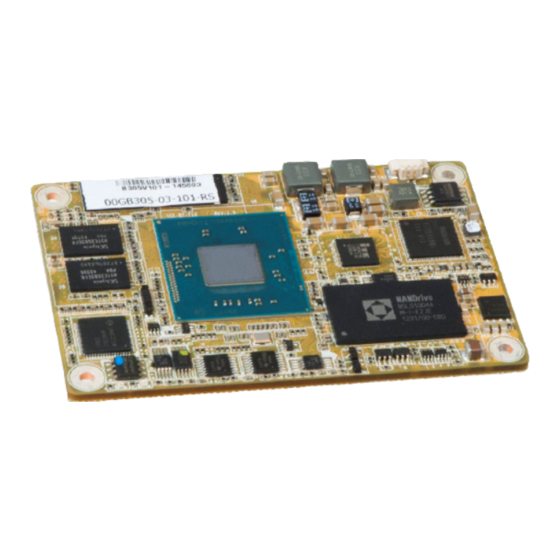
ICE-BT-T10 COM Express Module 1.1 Introduction Figure 1-1: ICE-BT-T10 The ICE-BT-T10 COM Express Type 10 module provides the main processing chips and is connected to a compatible COM Express baseboard. The ICE-BT-T10 is preinstalled with 4 generation Intel® Atom™ or Celeron® processor. The COM Express standard allows the COM Express baseboard to be designed, while leaving the choice of processor till the later stages of design. -
Page 13: Model Variations
Max. Memory Size Standard ICE-BT-T10-E38151 Intel® Atom™ processor E3815 4 GB (1.46 GHz, single-core, 512 KB cache) ICE-BT-T10-E38251 Intel® Atom™ processor E3825 4 GB (1.33 GHz, dual-core, 1 MB cache) By Request (MOQ: 100 pcs/lot) ICE-BT-T10-E38261 Intel® Atom™ processor E3826 8 GB (1.46 GHz, dual-core, 1 MB cache) -
Page 14: Board Overview
ICE-BT-T10 COM Express Module Optional on-board 4 GB SSD Supports analog CRT (VGA), DisplayPort and HDMI Supports USB 3.0, SATA 3Gb/s and GbE RoHS compliant 1.4 Board Overview The on-board components and connectors of the ICE-BT-T10 are shown in the figures below. -
Page 15: Dimensions
ICE-BT-T10 COM Express Module 1.5 Dimensions The main dimensions of the ICE-BT-T10 are shown in the diagram below. Figure 1-3: ICE-BT-T10 Dimensions (mm) Page 5... -
Page 16: Figure 1-4: Ice-Bt-T10 Heatsink Dimensions (Mm)
ICE-BT-T10 COM Express Module Figure 1-4: ICE-BT-T10 Heatsink Dimensions (mm) Page 6... -
Page 17: Data Flow
ICE-BT-T10 COM Express Module 1.6 Data Flow Figure 1-5 shows the data flow between the system chipset, the CPU and other components installed on the motherboard. Figure 1-5: Data Flow Diagram Page 7... -
Page 18: Technical Specifications
ICE-BT-T10 COM Express Module 1.7 Technical Specifications The ICE-BT-T10 technical specifications are listed below. ICE-BT-T10 Form Factor PICMG COM Express R2.1 Type 10 Standard Intel® Atom™ processor E3825 (1.33GHz, dual-core, 1MB cache, TDP=6W) Intel® Atom™ processor E3815 (1.46GHz, single-core, 512KB cache, TDP=5W)Intel® ... -
Page 19: Table 1-2: Ice-Bt-T10 Specifications
ICE-BT-T10 COM Express Module ICE-BT-T10 Two SATA 3Gb/s (signal to baseboard) Storage Optional on-board 4 GB SSD (SATA port1) One VGA via reserved pin (up to 2560 x 1600) Display One DDI (DP: up to 2560 x 1600; HDMI: up to 1920 x 1080) (Signal to Baseboard) One eDP Expansions... -
Page 20: Packing List
ICE-BT-T10 COM Express Module Chapter Packing List Page 10... -
Page 21: Anti-Static Precautions
ICE-BT-T10 COM Express Module 2.1 Anti-static Precautions WARNING! Static electricity can destroy certain electronics. Make sure to follow the ESD precautions to prevent damage to the product, and injury to the user. Make sure to adhere to the following guidelines: ... -
Page 22: Packing List
ICE-BT-T10 COM Express Module 2.3 Packing List NOTE: If any of the components listed in the checklist below are missing, do not proceed with the installation. Contact the IEI reseller or vendor the ICE-BT-T10 was purchased from or contact an IEI sales representative directly by sending an email to ales@ieiworld.com. -
Page 23: Optional Items
ICE-BT-T10 COM Express Module 2.4 Optional Items The following are optional components which may be separately purchased: Item and Part Number Image Baseboard for COM Express Type 10 modules (P/N: ICE-DB-T10-R10) Table 2-2: Optional Items Page 13... -
Page 24: Connectors
ICE-BT-T10 COM Express Module Chapter Connectors Page 14... -
Page 25: Peripheral Interface Connectors
ICE-BT-T10 COM Express Module 3.1 Peripheral Interface Connectors This chapter details all the connectors. 3.1.1 ICE-BT-T10 Layout The figure below shows all the connectors. Figure 3-1: Connectors (Solder Side) 3.1.2 Peripheral Interface Connectors The table below lists all the connectors on the ICE-BT-T10. Connector Type Label... -
Page 26: Internal Peripheral Connectors
ICE-BT-T10 COM Express Module 3.2 Internal Peripheral Connectors The section describes all of the connectors on the ICE-BT-T10. 3.2.1 COM Express Connector CN Label: COMEXPRESS_T10_AB1 220-pin COM Express connector CN Type: CN Location: See Figure 3-2 CN Pinouts: See Table 3-2 The standard COM Express connector location and pinouts are shown below. - Page 27 ICE-BT-T10 COM Express Module Pin No. Description Pin No. Description GBE0_MDI1+ LPC_CLK GND1 GND16 GBE0_MDI0- PWRBTN# GBE0_MDI0+ SMB_CK GBE0_CTREF SMB_DAT SUS_S3# SMB_ALERT# SATA0_TX+ SATA1_TX+ SATA0_TX- SATA1_TX- SUS_S4# SUS_STAT# SATA0_RX+ SATA1_RX+ SATA0_RX- SATA1_RX- GND2 GND17 USB_SSRX0- USB_SSTX0- USB_SSRX0+ USB_SSTX0+ RSVD RSVD RSVD RSVD RSVD...
- Page 28 ICE-BT-T10 COM Express Module Pin No. Description Pin No. Description USB2- USB3- USB2+ USB3+ USB_2_3_OC# USB_0_1_OC# USB0- USB1- USB0+ USB1+ VCC_RTC RSVD RSVD RSVD RSVD SYS_RESET# LPC_SERIRQ CB_RESET# GND5 GND20 VGA_HSYNC RSVD VGA_VSYNC VGA_RED GPI0 GPO1 VGA_I2C_CK VGA_GRN VGA_I2C_DAT VGA_BLU GND6 GPO2 RSVD...
- Page 29 ICE-BT-T10 COM Express Module Pin No. Description Pin No. Description DDI0_TXN1 (eDP) DDI1_TXN1 DDI0_TXP0 (eDP) DDI1_TXP0 DDI0_TXN0 (eDP) DDI1_TXN0 DDI0_ENVDD (eDP) RSVD RSVD RSVD RSVD DDI0_ENBKL GND10 GND23 DDI0_TXP3 (eDP) DDI1_TXP3 DDI0_TXN3 (eDP) DDI1_TXN3 DDI0_AUXP (eDP) DDI0_PWM (eDP) DDI0_AUXN (eDP) VCC5SBY GPI3 VCC5SBY...
-
Page 30: Spi Flash Connector
ICE-BT-T10 COM Express Module Pin No. Description Pin No. Description VCC_12V B106 VCC_12V A106 VCC_12V B107 VCC_12V A107 VCC_12V B108 VCC_12V A108 VCC_12V B109 VCC_12V A109 GND14 B110 GND26 A110 Table 3-2: COM Express Connector Pin Definitions 3.2.2 SPI Flash Connector CN Label: JSPI1 CN Type:... -
Page 31: Installation
ICE-BT-T10 COM Express Module Chapter Installation Page 21... -
Page 32: Anti-Static Precautions
ICE-BT-T10 COM Express Module 4.1 Anti-static Precautions WARNING: Failure to take ESD precautions during the installation of the ICE-BT-T10 may result in permanent damage to the ICE-BT-T10 and severe injury to the user. Electrostatic discharge (ESD) can cause serious damage to electronic components, including the ICE-BT-T10. - Page 33 ICE-BT-T10 COM Express Module WARNING: The installation instructions described in this manual should be carefully followed in order to prevent damage to the components and injury to the user. Before and during the installation please DO the following: Read the user manual: The user manual provides a complete description of the ICE-BT-T10 installation instructions and configuration options.
-
Page 34: Mounting Ice-Bt-T10 To Baseboard
ICE-BT-T10 COM Express Module 4.3 Mounting ICE-BT-T10 to Baseboard NOTE: Baseboard can be designed by the end user, customized by IEI, or purchased from IEI. For more information visit the IEI website (www.ieiworld.com) or contact an IEI sales representative. WARNING: Never run the COM Express module without the heatsink and a thermal pad. -
Page 35: Figure 4-1: Connect The Com Express Connectors
ICE-BT-T10 COM Express Module Figure 4-1: Connect the COM Express Connectors Step 2: Ensure a thermal pad is placed on the CPU of the ICE-BT-T10. Step 3: Place the heatsink on the ICE-BT-T10, aligning the retention screw holes (Figure 4-2). Step 4: Secure the heatsink to the ICE-BT-T10 and the baseboard with the supplied retention screws (Figure 4-2). -
Page 36: Figure 4-2: Secure The Heatsink
ICE-BT-T10 COM Express Module Figure 4-2: Secure the Heatsink Page 26... -
Page 37: Bios
ICE-BT-T10 COM Express Module Chapter BIOS Page 27... -
Page 38: Introduction
ICE-BT-T10 COM Express Module 5.1 Introduction The BIOS is programmed onto the BIOS chip. The BIOS setup program allows changes to certain system settings. This chapter outlines the options that can be changed. 5.1.1 Starting Setup The UEFI BIOS is activated when the computer is turned on. The setup program can be activated in one of two ways. -
Page 39: Getting Help
ICE-BT-T10 COM Express Module Function Esc key Main Menu – Quit and not save changes into CMOS Status Page Setup Menu and Option Page Setup Menu -- Exit current page and return to Main Menu General help, only for Status Page Setup Menu and Option Page Setup Menu Load previous values Load optimized defaults... -
Page 40: Main
ICE-BT-T10 COM Express Module 5.2 Main The Main BIOS menu (BIOS Menu 1) appears when the BIOS Setup program is entered. The Main menu gives an overview of the basic system information. Aptio Setup Utility – Copyright (C) 2013 American Megatrends, Inc. Main Advanced Chipset... -
Page 41: Advanced
ICE-BT-T10 COM Express Module Use the System Time option to set the system time. Manually enter the hours, minutes and seconds. 5.3 Advanced Use the Advanced menu (BIOS Menu 2) to configure the CPU and peripheral devices through the following sub-menus: WARNING: Setting the wrong values in the sections below may cause the system to malfunction. -
Page 42: Bios Menu 3: Acpi Settings
ICE-BT-T10 COM Express Module Aptio Setup Utility – Copyright (C) 2013 American Megatrends, Inc. Advanced ACPI Settings Select ACPI sleep state the system will enter ACPI Sleep State [S3 (Suspend to RAM)] when the SUSPEND button is pressed. ---------------------- : Select Screen ... -
Page 43: It8587 Super Io Configuration
ICE-BT-T10 COM Express Module 5.3.2 IT8587 Super IO Configuration Use the IT8587 Super IO Configuration menu (BIOS Menu 4) to set or change the configurations for the serial ports. Aptio Setup Utility – Copyright (C) 2013 American Megatrends, Inc. Advanced IT8587 Super IO Configuration Set Parameters of Serial Port 1 (COMA) - Page 44 ICE-BT-T10 COM Express Module 5.3.2.1.1 Serial Port 1 Configuration Serial Port [Enabled] Use the Serial Port option to enable or disable the serial port. Disabled Disable the serial port Enable the serial port Enabled EFAULT Change Settings [Auto] Use the Change Settings option to change the serial port IO port address and interrupt address.
- Page 45 ICE-BT-T10 COM Express Module 5.3.2.1.2 Serial Port 2 Configuration Serial Port [Enabled] Use the Serial Port option to enable or disable the serial port. Disabled Disable the serial port Enable the serial port Enabled EFAULT Change Settings [Auto] Use the Change Settings option to change the serial port IO port address and interrupt address.
-
Page 46: Iwdd H/W Monitor
ICE-BT-T10 COM Express Module 5.3.3 iWDD H/W Monitor The iWDD H/W Monitor menu (BIOS Menu 6) displays the CPU temperature and CPU fan speed, and contains the fan configuration submenu. Aptio Setup Utility – Copyright (C) 2013 American Megatrends, Inc. Advanced PC Health Status Smart Fan Mode Select... -
Page 47: Smart Fan Mode Configuration
ICE-BT-T10 COM Express Module 5.3.3.1 Smart Fan Mode Configuration Use the Smart Fan Mode Configuration submenu (BIOS Menu 7) to configure the smart fan temperature and speed settings. Aptio Setup Utility – Copyright (C) 2013 American Megatrends, Inc. Advanced Smart Fan Mode Configuration Smart Fan Mode Select CPU_FAN1 Smart Fan Control [Auto Mode]... -
Page 48: Rtc Wake Settings
ICE-BT-T10 COM Express Module Auto mode fan slope PWM Use the + or – key to change the Auto mode fan slope PWM value. Enter a decimal number between 1 and 64. 5.3.4 RTC Wake Settings The RTC Wake Settings menu (BIOS Menu 8) enables the system to wake at the specified time. -
Page 49: Serial Port Console Redirection
ICE-BT-T10 COM Express Module following options appear with values that can be selected: Wake up date Wake up hour Wake up minute Wake up second After setting the alarm, the computer turns itself on from a suspend state when the alarm goes off. 5.3.5 Serial Port Console Redirection The Serial Port Console Redirection menu (BIOS Menu 9) allows the console redirection options to be configured. - Page 50 ICE-BT-T10 COM Express Module Enabled Enabled the console redirection function NOTE: The following five options appear when the Console Redirection option is enabled. Terminal Type [ANSI] Use the Terminal Type option to specify the remote terminal type. The target terminal type is VT100 VT100 ...
- Page 51 ICE-BT-T10 COM Express Module Sets the data bits at 7. Sets the data bits at 8. EFAULT Parity [None] Use the Parity option to specify the parity bit that can be sent with the data bits for detecting the transmission errors.
-
Page 52: Cpu Configuration
ICE-BT-T10 COM Express Module 5.3.6 CPU Configuration Use the CPU Configuration menu (BIOS Menu 10) to view detailed CPU specifications and configure the CPU. Aptio Setup Utility – Copyright (C) 2013 American Megatrends, Inc. Advanced CPU Configuration Enabled for Windows XP and Linux (OS optimized Intel(R) Atom(TM) CPU E3825 @ 1.33GHz for Hyper-Threading... - Page 53 ICE-BT-T10 COM Express Module L1 Data Cache: Lists the amount of data storage space on the L1 cache. L1 Code Cache: Lists the amount of code storage space on the L1 cache. L2 Cache: Lists the amount of storage space on the L2 cache. ...
-
Page 54: Ide Configuration
ICE-BT-T10 COM Express Module 5.3.7 IDE Configuration Use the IDE Configuration menu (BIOS Menu 11) to change and/or set the configuration of the SATA devices installed in the system. Aptio Setup Utility – Copyright (C) 2013 American Megatrends, Inc. Advanced IDE Configuration Enable or disable SATA Device. -
Page 55: Sdio Configuration
ICE-BT-T10 COM Express Module 5.3.8 SDIO Configuration Use the SDIO Configuration menu (BIOS Menu 12) to configure the SD card slot. Aptio Setup Utility – Copyright (C) 2013 American Megatrends, Inc. Advanced SDIO Configuration Auto Option: Access SD device in DMA mode if SDIO Access Mode [Auto] controller supports it,... -
Page 56: Usb Configuration
ICE-BT-T10 COM Express Module 5.3.9 USB Configuration Use the USB Configuration menu (BIOS Menu 13) to read USB configuration information and configure the USB settings. Aptio Setup Utility – Copyright (C) 2013 American Megatrends, Inc. Advanced USB Configuration Enables Legacy USB support. -
Page 57: Chipset
ICE-BT-T10 COM Express Module Disabled Legacy USB support disabled Legacy USB support disabled if no USB devices are Auto connected 5.4 Chipset Use the Chipset menu (BIOS Menu 14) to access the North Bridge and South Bridge configuration menus. WARNING! Setting the wrong values for the Chipset BIOS selections in the Chipset BIOS menu may cause the system to malfunction. -
Page 58: North Bridge
ICE-BT-T10 COM Express Module 5.4.1 North Bridge Use the North Bridge menu (BIOS Menu 15) to configure the north bridge parameters. Aptio Setup Utility – Copyright (C) 2013 American Megatrends, Inc. Chipset > Intel IGD Configuration Config Intel IGD Settings. Memory Information Total Memory 2048 MB (LPDDR3) -
Page 59: Intel Igd Configuration
ICE-BT-T10 COM Express Module 5.4.1.1 Intel IGD Configuration Use the Intel IGD Configuration submenu (BIOS Menu 16) to configure the graphics settings. Aptio Setup Utility – Copyright (C) 2013 American Megatrends, Inc. Chipset Intel IGD Configuration Select which of IGFX/PEG/PCI Graphics Primary Display [IGD] device should be Primary... - Page 60 ICE-BT-T10 COM Express Module 128M 256M Default 512M DVMT Total Gfx Mem [MAX] Use the DVMT Total Gfx Mem option to select DVMT5.0 total graphic memory size used by the internal graphic device. The following options are available: ...
-
Page 61: South Bridge Configuration
ICE-BT-T10 COM Express Module 5.4.2 South Bridge Configuration Use the South Bridge menu ( B IOS Menu 17) to configure the south bridge chipset. Aptio Setup Utility – Copyright (C) 2013 American Megatrends, Inc. Chipset Auto Power Button Status [Enabled (AT)] Select AC power state when power is re-applied Restore AC Power Loss... -
Page 62: Pci Express Configuration
ICE-BT-T10 COM Express Module Enabled The High Definition Audio controller is enabled. EFAULT XHCI Mode [Enabled] Use the XHCI Mode BIOS option to configure the USB xHCI (USB 3.0) controller. Enable the xHCI controller. USB 3.0 ports behave as Enabled EFAULT USB 3.0 ports. -
Page 63: Security
ICE-BT-T10 COM Express Module Disabled The PCI Express slot is disabled. PCIe Speed Use PCIe Speed option to select the speed type of the PCI Express slots. The following options are available: Auto Default Gen1 Gen2 5.5 Security Use the Security menu (BIOS Menu 19) to set system and user passwords. -
Page 64: Boot
ICE-BT-T10 COM Express Module 5.6 Boot Use the Boot menu (BIOS Menu 20) to configure system boot options. Aptio Setup Utility – Copyright (C) 2013 American Megatrends, Inc. Main Advanced Chipset Security Boot Save & Exit Boot Configuration Select the keyboard Bootup NumLock State [On] NumLock state... - Page 65 ICE-BT-T10 COM Express Module Quiet Boot [Enabled] Use the Quiet Boot BIOS option to select the screen display when the system boots. Normal POST messages displayed Disabled Enabled OEM Logo displayed instead of POST messages EFAULT UEFI Boot [Disabled] Use the UEFI Boot BIOS option to allow the system to boot from the UEFI devices.
-
Page 66: Save & Exit
ICE-BT-T10 COM Express Module 5.7 Save & Exit Use the Save & Exit menu (BIOS Menu 21) to load default BIOS values, optimal failsafe values and to save configuration changes. Aptio Setup Utility – Copyright (C) 2013 American Megatrends, Inc. Main Advanced Chipset... - Page 67 ICE-BT-T10 COM Express Module Restore Defaults Use the Restore Defaults option to load the optimal default values for each of the parameters on the Setup menus. F3 key can be used for this operation. Save as User Defaults Use the Save as User Defaults option to save the changes done so far as user defaults.
-
Page 68: Software Drivers
ICE-BT-T10 COM Express Module Chapter Software Drivers Page 58... -
Page 69: Available Software Drivers
ICE-BT-T10 COM Express Module 6.1 Available Software Drivers NOTE: The content of the CD may vary throughout the life cycle of the product and is subject to change without prior notice. Visit the IEI website or contact technical support for the latest updates. The following drivers can be installed on the system: ... -
Page 70: Figure 6-1: Start Up Screen
ICE-BT-T10 COM Express Module Figure 6-1: Start Up Screen Step 3: Click ICE-BT-T10. Step 4: The list of drivers in Figure 6-2 appears. Figure 6-2: Drivers Page 60... -
Page 71: Chipset Driver Installation
ICE-BT-T10 COM Express Module 6.3 Chipset Driver Installation To install the chipset driver, please do the following. Step 1: Access the driver list. (See Section 6.2) Step 2: Click “1-Bay Trail SOC” and select the folder which corresponds to the operating system. -
Page 72: Figure 6-4: Chipset Driver License Agreement
ICE-BT-T10 COM Express Module Step 6: Click Yes to accept the agreement and continue. Figure 6-4: Chipset Driver License Agreement Step 7: The Read Me file in Figure 6-5 appears. Step 8: Click Next to continue. Figure 6-5: Chipset Driver Read Me File Page 62... -
Page 73: Figure 6-6: Chipset Driver Setup Operations
ICE-BT-T10 COM Express Module Step 9: Setup Operations are performed as shown in Figure 6-6. Step 10: Once the Setup Operations are complete, click Next to continue. Figure 6-6: Chipset Driver Setup Operations Step 11: The Finish screen in Figure 6-7 appears. Step 12: Select “Yes, I want to restart this computer now”... -
Page 74: Graphics Driver Installation
ICE-BT-T10 COM Express Module 6.4 Graphics Driver Installation To install the graphics driver, please do the following. Step 1: Access the driver list. (See Section 6.2) Step 2: Click “1-Bay Trail SOC” and select the folder which corresponds to the operating system. -
Page 75: Figure 6-8: Graphics Driver License Agreement
ICE-BT-T10 COM Express Module Figure 6-8: Graphics Driver License Agreement Step 6: The License Agreement in Figure 6-9 appears. Step 7: Click Yes to accept the agreement and continue. Figure 6-9: Graphics Driver Read Me File Step 8: The Read Me file in Figure 6-10 appears. Click Next to continue. Page 65... -
Page 76: Figure 6-10: Graphics Driver Setup Operations
ICE-BT-T10 COM Express Module Figure 6-10: Graphics Driver Setup Operations Step 9: Setup Operations are performed as shown in Figure 6-11. Step 10: Once the Setup Operations are complete, click Next to continue. Figure 6-11: Graphics Driver Installation Finish Screen Step 11: The system starts installing the Graphics Driver. -
Page 77: Lan Driver Installation
ICE-BT-T10 COM Express Module Step 13: Select “Yes, I want to restart this computer now” and click Finish. Step 0: Figure 6-12: Graphics Driver Installation Finish Screen 6.5 LAN Driver Installation To install the LAN driver, please do the following. Step 1: Right-click the Computer button from the start menu and select Properties (Figure 6-13). -
Page 78: Figure 6-13: Windows Control Panel
ICE-BT-T10 COM Express Module Figure 6-13: Windows Control Panel Step 2: The system control panel window in Figure 6-14 appears. Step 3: Click the Device Manager link (Figure 6-14). Figure 6-14: System Control Panel Page 68... -
Page 79: Figure 6-15: Device Manager List
ICE-BT-T10 COM Express Module Step 4: A list of system hardware devices appears (Figure 6-15). Step 5: Right-click the Ethernet Controller that has question marks next to it (this means Windows does not recognize the device). Step 6: Select Update Driver Software. Figure 6-15: Device Manager List Step 7: The Update Driver Software Window appears (Figure 6-16). -
Page 80: Figure 6-16: Update Driver Software Window
ICE-BT-T10 COM Express Module Figure 6-16: Update Driver Software Window Step 8: Select “Browse my computer for driver software” and click N to continue. Step 9: Click Browse to select “X:\2-LAN\Intel” directory in the Locate File window, where “X:\” is the system CD drive. (Figure 6-17). Figure 6-17: Locate Driver Files Step 10: Click N... - Page 81 ICE-BT-T10 COM Express Module Step 11: Driver Installation is performed. When the Finish screen appears, click Close to exit. Step 12: Right-click the other Ethernet controller that has question marks next to it as shown in Figure 6-15. Repeat Step 6–Step 11 to install the second Ethernet controller driver.
-
Page 82: A Regulatory Compliance
ICE-BT-T10 COM Express Module Appendix Regulatory Compliance Page 72... - Page 83 ICE-BT-T10 COM Express Module DECLARATION OF CONFORMITY This equipment has been tested and found to comply with specifications for CE marking. If the user modifies and/or installs other devices in the equipment, the CE conformity declaration may no longer apply. FCC WARNING This equipment complies with Part 15 of the FCC Rules.
-
Page 84: Bbios Options
ICE-BT-T10 COM Express Module Appendix BIOS Options Page 74... - Page 85 ICE-BT-T10 COM Express Module Below is a list of BIOS configuration options in the BIOS chapter. System Date [xx/xx/xx] ......................30 System Time [xx:xx:xx] .......................30 ACPI Sleep State [S3 (Suspend to RAM)]................32 Serial Port [Enabled]......................34 Change Settings [Auto] .......................34 ...
- Page 86 ICE-BT-T10 COM Express Module Audio Controller [Enabled] ....................51 XHCI Mode [Enabled]......................52 PCI Express Port 2 [Enabled] .....................52 PCIe Speed ...........................53 Administrator Password .....................53 User Password ........................53 Bootup NumLock State [On]....................54 Quiet Boot [Enabled] ......................55 ...
-
Page 87: C Terminology
ICE-BT-T10 COM Express Module Appendix Terminology Page 77... - Page 88 ICE-BT-T10 COM Express Module AC ’97 Audio Codec 97 (AC’97) refers to a codec standard developed by Intel® in 1997. ACPI Advanced Configuration and Power Interface (ACPI) is an OS-directed configuration, power management, and thermal management interface. AHCI Advanced Host Controller Interface (AHCI) is a SATA Host controller register-level interface.
- Page 89 ICE-BT-T10 COM Express Module DIMM Dual Inline Memory Modules are a type of RAM that offer a 64-bit data bus and have separate electrical contacts on each side of the module. The digital inputs and digital outputs are general control signals that control the on/off circuit of external devices or TTL devices.
- Page 90 ICE-BT-T10 COM Express Module LVDS Low-voltage differential signaling (LVDS) is a dual-wire, high-speed differential electrical signaling system commonly used to connect LCD displays to a computer. POST The Power-on Self Test (POST) is the pre-boot actions the system performs when the system is turned-on. Random Access Memory (RAM) is volatile memory that loses data when power is lost.
- Page 91 ICE-BT-T10 COM Express Module Appendix Watchdog Timer Page 81...
- Page 92 ICE-BT-T10 COM Express Module NOTE: The following discussion applies to DOS environment. Contact IEI support or visit the IEI website for specific drivers for other operating systems. The Watchdog Timer is provided to ensure that standalone systems can always recover from catastrophic conditions that cause the CPU to crash.
- Page 93 ICE-BT-T10 COM Express Module NOTE: When exiting a program it is necessary to disable the Watchdog Timer, otherwise the system resets. EXAMPLE PROGRAM: ; INITIAL TIMER PERIOD COUNTER W_LOOP: AX, 6F02H ;setting the time-out value BL, 30 ;time-out value is 48 seconds ;...
- Page 94 ICE-BT-T10 COM Express Module Appendix Hazardous Materials Disclosure Page 84...
- Page 95 ICE-BT-T10 COM Express Module E.1 Hazardous Materials Disclosure Table for IPB Products Certified as RoHS Compliant Under 2002/95/EC Without Mercury The details provided in this appendix are to ensure that the product is compliant with the Peoples Republic of China (China) RoHS standards. The table below acknowledges the presences of small quantities of certain materials in the product, and is applicable to China RoHS only.
- Page 96 ICE-BT-T10 COM Express Module Part Name Toxic or Hazardous Substances and Elements Lead Mercury Cadmium Hexavalent Polybrominated Polybrominated (Pb) (Hg) (Cd) Chromium Biphenyls Diphenyl (CR(VI)) (PBB) Ethers (PBDE) Housing Display Printed Circuit Board Metal Fasteners Cable Assembly Fan Assembly Power Supply Assemblies Battery This toxic or hazardous substance is contained in all of the homogeneous materials for the part is...
- Page 97 ICE-BT-T10 COM Express Module 此附件旨在确保本产品符合中国 RoHS 标准。以下表格标示此产品中某有毒物质的含量符 合中国 RoHS 标准规定的限量要求。 本产品上会附有”环境友好使用期限”的标签,此期限是估算这些物质”不会有泄漏或突变”的 年限。本产品可能包含有较短的环境友好使用期限的可替换元件,像是电池或灯管,这些元 件将会单独标示出来。 部件名称 有毒有害物质或元素 铅 汞 镉 六价铬 多溴联苯 多溴二苯 醚 (Pb) (Hg) (Cd) (CR(VI)) (PBB) (PBDE) 壳体 显示 印刷电路板 金属螺帽 电缆组装 风扇组装 电力供应组装 电池 O: 表示该有毒有害物质在该部件所有物质材料中的含量均在 SJ/T11363-2006 标准规定的限量要求以下。 X: 表示该有毒有害物质至少在该部件的某一均质材料中的含量超出...
Need help?
Do you have a question about the ICE-BT-T10-E38251 and is the answer not in the manual?
Questions and answers