Table of Contents

Related Manuals for Teka FilterCube 4-IFA


Summary of Contents for Teka FilterCube 4-IFA
- Page 1 Operating instructions (Translation of the original operating instructions) FilterCube 4 - IFA TEKA Absaug- und Entsorgungstechnologie GmbH, Millenkamp 9, D-48653 Coesfeld, Tel.: +49 2541-84841-0, E-Mail: info@teka.eu, www.teka.eu...
-
Page 2: Table Of Contents
7.4. Emptying the dust collecting tank 7.5. Draining the condensate 7.6. Precoating of new filter cartridges 7.6.1. Feeding the precoat via a FVS (TEKA spark pre-separator) 7.7. Cleaning/replacing the particle sensor 7.8. Replacing the filter mats at the control cabinet 8. -
Page 3: General
14.2.6. Test of fixing of the mounted unit elements 1. General Congratulations on purchasing the product from TEKA. Our engineers ensure that our devices reflect the state of the art through continuous development. Nevertheless, misuse or misconduct can endanger your safety. Please observe the following for a... -
Page 4: Description Of The System Elements
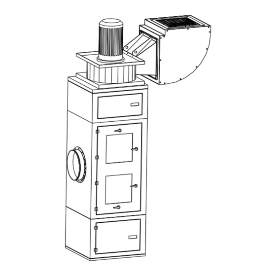
2. Description of the system elements 2.1. Illustration of the system elements Installation example: Z.Nr. 21382701 Pos.1 Dust collecting housing Pos.5 Suction nozzle Pos.2 Filter housing Pos.6 Exhaust air nozzle Pos.3 Cleaning housing Pos.7 Connection for compressed air Pos.4 Pos.8 Drain valve for compressed air Pos.9 Silencer... -
Page 5: Intended Use
2.3. Intended use The device is intended for commercial use. If the device is made publicly accessible, it must never be operated unsupervised by authorized personnel, authorized by the operator. The filter unit is intended for extraction and filtration of dusts and fumes that result from thermal joining and cutting of metals. -
Page 6: General Safety Instructions
NOTICE NOTICE These instructions are made in case of risks that can lead to material damages. Information notes are no hazard warnings; they call attention to useful information. 3.2. General safety instructions WARNING Dangers arising from improper use / unauthorised operations. The operator must ensure that their authorised personnel are familiar with all the safety indications in this manual in advance. -
Page 7: Storage, Transport And Installation Of The Device
4. Storage, transport and installation of the device WARNING Risk of injury from tilting or unmounted components when stored or transported. The device must be secured against tilting and slipping when it is stored or transported. Do not stand under or next to the floating load. Lift trucks, forklift trucks and transport cranes must have a sufficient minimum load bearing capacity. -
Page 8: Commissioning
5. Commissioning WARNING Dangers arising from a defective condition of the unit. Make sure that the measures described in this chapter are completed before the commissioning of the unit. All doors of the unit must be closed and all necessary connections must be attached before turning the unit on. -
Page 9: Connecting The Suction Line And Exhaust Air Line
If this has not already been carried out by TEKA, a suitably qualified employee must be consulted. If the suction line includes extraction elements (e.g. suction arms, pipe grills, etc.), these must also be included in the layout. -
Page 10: Electrical Connection
5.2. Electrical connection WARNING Risk of electric shock. Electrical plants and equipment may only be built, modified and maintained by a qualified electrician or under the direction and supervision of a qualified electrician. Do not work on live electrical components and elements if you are not sure that these are indeed disconnected. -
Page 11: Precoating Of The Filter Cartridges
5.3. Precoating of the filter cartridges For a longer service life of the filter cartridges they are pretreated with a filter aid in the factory. If the fan unit and the filter unit of the filter device are only connected to one another on site, then the filter cartridges have not yet been pretreated at the factory. -
Page 12: Operating The System
6. Operating the system 6.1. Explanation of the operating elements Control functions, setting options for programs, menu navigation, error messages, etc. are described in the enclosed operating manual of the unit control. There is also an explanation of the elements of the control panel. Operating elements for the device control Representa Designation... -
Page 13: Maintenance
7. Maintenance In accordance with national regulations, the operator is obliged to carry out repeat and functional tests. Unless otherwise specified by national regulations, we recommend regular visual inspections and functional tests of the device as described in the chapter “Maintenance intervals”. You find the chapter “Maintenance intervals”... -
Page 14: Reset To Maintenance State
7.1 Reset to maintenance state ● Switch off the unit. Then disconnect the unit from the power supply by setting the main switch in the “OFF” position. Secure the unit against unauthorized restarting during maintenance. ● Disconnect the compressed air hose of the external compressed air supply from the insert sleeve (see chapter 2.1). -
Page 15: Cleaning The Filter Cartridges
7.2. Cleaning the filter cartridges CAUTION A sudden jet of compressed air and huge amounts of whirled up dust are possible due to an automatic cleaning with an opened service door. During the operation of the device, the service door of the filter housing must not be opened. The same applies to the ready to operate condition (standby) as there is also the possibility of an automatic cleaning (subsequent cleaning). -
Page 16: Replacing The Filter Cartridges
7.3. Replacing the filter cartridges Replacing the filter cartridges becomes necessary when the filter cartridges are saturated with dirt in a manner that despite of the cleaning the filter alarm is triggered again at very short intervals or permanently. (The filter alarm is described in chapter “Cleaning the filter cartridges”.) CAUTION Whirling up dust is possible due to the polluted filter cartridges. - Page 17 ● We recommend that two people work together to replace the filter cartridges. ● We recommend spreading out a protective film in order to keep the area around the unit clean. ● The filter cartridges may only be replaced in well-ventilated rooms and while wearing an appropriate respiratory mask! We recommend: Respiratory protection half mask DIN EN 141/143...
- Page 18 ● Pull the disposal bag over the cartridge holder and filter cartridge. ● Unhook the cartridge holder from the cartridge guides. ● Remove the cartridge holder with the filter cartridge and the disposal bag from the filter housing. ● Briefly lift the filter cartridge in order to release it from the cartridge holder.
- Page 19 ● First of all, remove all the filter cartridges as described in the steps above. ● Only then should you start to install the new filter cartridges. Only use TEKA replacement filters. Otherwise the correct functioning of the unit is not guaranteed.
- Page 20 ● Insert the displacer into the new filter cartridge in such a way that the displacer’s screw passes through the opening in the base of the filter cartridge. Check whether the seal is in contact at the thread of the displacer and that it is undamaged.
- Page 21 ● Insert the new filter cartridge in the cartridge holder. When you do this, the cylindrical nut must be placed on the fixing screw. ● Then insert the second, loose side of the cartridge holder in the corresponding cartridge guide. ●...
-
Page 22: Emptying The Dust Collecting Tank
Before emptying the dust collecting tank hold ready an appropriate container (e.g. PE bag). The bags are optionally available at TEKA, see list of spare parts. We recommend having PE bags in stock. ●... -
Page 23: Draining The Condensate
● Place a new dust collection bag in the dust collection container so that the bag is put over the edge of the dust collection container. Therefore place the slip-on frame back on the dust collecting tank. ● Push the dust collecting tank back into the dust collecting housing. ●... -
Page 24: Precoating Of New Filter Cartridges
● Provide sufficient filter aid. We recommend using 10 grams for each square metre of the filter surface. The filter aid is available at TEKA (see list of spare parts). ● Choose the capture point in the suction pipe that is the closest to the filter cartridges. E.g. an inspection flap can be used as a capture point. -
Page 25: Feeding The Precoat Via A Fvs (Teka Spark Pre-Separator)
7.6.1. Feeding the precoat via a FVS (TEKA spark pre-separator) This chapter is only relevant if the filter unit is equipped with a FVS (TEKA spark pre-separator). A FVS is a water separator installed in the suction pipe of the filter unit. -
Page 26: Cleaning/Replacing The Particle Sensor
If the controller now still reports a “particle sensor” error message then the detector head must be replaced. Replacement parts are available from TEKA, see the spare parts list. In this case, it is not necessary to replace the assembly base which is screwed to the unit. -
Page 27: Replacing The Filter Mats At The Control Cabinet
● Replace the old filter mat with a new one. The blue side must face outwards. Only use TEKA spare filters. Otherwise the proper functioning of the unit is not guaranteed. ● Close the louvred grille until it audibly clicks into place. -
Page 28: Dismantling / Disposal
A recommissioning of the device must only occur if it is ensured that the system is functionally equivalent to the original state. Repairs may only be carried out by TEKA personnel or, after consultation with TEKA GmbH, by the personnel authorised by the operator. - Page 29 Dust at the dust There is too much dust in the dust Empty the dust collecting tank. collecting tank. collection container. The toggle closures are not closed. Close the toggle closers. The seal of the dust collecting tank is The seal must be replaced. damaged.
-
Page 30: List Of Spare Parts
10. List of spare parts Below, you will find a list of the various filter cartridges that can be installed in units of this type. We recommend that you order the filter cartridges that were supplied on initial delivery of the unit. Otherwise, the cleaning performance or lifetime of the filter cartridges may be impaired (due to differences in the filter material or filter surface area). -
Page 31: Technical Data
11. Technical data Version 2,2 - 4,0 kW 5,5 - 11,0 kW Supply voltage Frequency Type of current 3 Ph + N + PE engine power 11,0 Air flow volume max. m³/h 3500 4000 5000 6000 7500 10000 Negative pressure max. 2900 3300 3600... -
Page 32: Ec Declaration Of Conformity
This declaration will become void if the device is exposed to modifications that are not approved by the manufacturer in written form. Authorized representative for the technical documentation: TEKA Absaug- und Entsorgungstechnologie GmbH, Millenkamp 9, D-48653 Coesfeld (Jürgen Kemper, managing director) Coesfeld, 3rd january 2023 BA_FilterCube_4_IFA_20230808_EN 08.08.2023... -
Page 33: Training Protocol
13. Training protocol Designation of the device: FilterCube 4 - IFA (This form can be used by the operator to document the training of the employees. Training should be performed by authorized personnel only. Refer to the instructions in Chapter "Safety Instructions") By his signature, the employee confirms that he has been instructed regarding the following items: Instruction completed... -
Page 34: Maintenance Intervals
The approach of the maintenance measures is described in chapter "Maintenance". Maintenance interval Maintenance work Chapter recommended by TEKA determined by the operator The cleaning of the filter cartridges is automatically carried out Cleaning the filter cartridges by the filter unit and thus is not subject to a maintenance interval. -
Page 35: General Maintenance
14.2. General maintenance The described maintenances are independent from the demands of the system operations. The operator is obliged to carry out repeated inspections and functional tests according to national regulations. If not otherwise covered by national regulations, the described maintenance intervals must be respected. -
Page 36: Visual Inspection Of The Pipelines For Dust Deposits
14.2.2. Visual inspection of the pipelines for dust deposits Visual inspection: Observation that there are no visible safety-related defects. WARNING Danger arising from the ready to operate condition of the device. Follow the procedure as described in the chapter “Set to maintenance state”. The following steps must be carried out in the course of the visual inspection: ●... -
Page 37: Electrical Test Of The Electrical Lines And Earthing Connections
● A functional test should always be carried out with a connected / producing machine tool. Check if the collection of the fume or dust is sufficient. (Visual inspection). 14.2.5. Electrical test of the electrical lines and earthing connections WARNING Danger arising from electricity.
Need help?
Do you have a question about the FilterCube 4-IFA and is the answer not in the manual?
Questions and answers