Table of Contents
Advertisement
Quick Links
Scroll Pumps
XDS35i, XDS35iC, XDS35iR, XDS35iE,
XDS35iCE and XDS35iRE
INSTRUCTION MANUAL
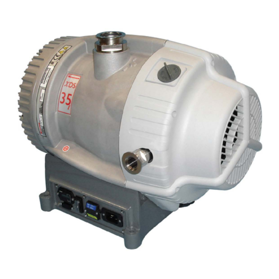
DESCRIPTION
XDS35i Scroll Pump (set to high volts)
XDS35i Scroll Pump (set to low volts)
XDS35i Scroll Pump
XDS35iC Scroll Pump Chemical
XDS35iR Scroll Pump (No Gas Ballast)
XDS35iE Scroll Pump Enhanced
XDS35iCE Scroll Pump Enhanced Chemical
XDS35iRE Scroll Pump Enhanced (No Gas Ballast)
A73001880_P
edwardsvacuum.com
ITEM NUMBER
A730YY983
A730YY986
A73001983
A73006983
A73005983
A73003983
A73008983
A73007983
Original instructions
Advertisement
Table of Contents

Subscribe to Our Youtube Channel
Related Manuals for Edwards XDS35iR


Summary of Contents for Edwards XDS35iR
- Page 1 XDS35i Scroll Pump (set to low volts) A730YY986 XDS35i Scroll Pump A73001983 XDS35iC Scroll Pump Chemical A73006983 XDS35iR Scroll Pump (No Gas Ballast) A73005983 XDS35iE Scroll Pump Enhanced A73003983 XDS35iCE Scroll Pump Enhanced Chemical A73008983 XDS35iRE Scroll Pump Enhanced (No Gas Ballast)
- Page 2 Copyright notice ©Edwards Limited 2022. All rights reserved. Trademark credit Edwards and the Edwards logo are trademarks of Edwards Limited, Innovation Drive, Burgess Hill, West Sussex RH15 9TW. Associated publications Publication title Publication number Vacuum Pump and Vacuum System Safety...
-
Page 3: Table Of Contents
5.5.1 Flammable materials........24 A73001880_P Page 3 05/2022 - ©Edwards Limited... - Page 4 10. Legal declarations........38 A73001880_P Page 4 05/2022 - ©Edwards Limited...
- Page 5 Figure 7: Gas ballast control assembly......... . 30 A73001880_P Page 5 05/2022 - ©Edwards Limited...
-
Page 6: Safety And Compliance
Information about properties or instructions for an action which, if ignored, will cause damage to the equipment. We reserve the right to change the design and the stated data. The illustrations are not binding. Keep the instructions for future use. A73001880_P Page 6 05/2022 - ©Edwards Limited... -
Page 7: Safety Symbols
Warning - Dangerous voltage Identifies possible hazards from hazardous voltages. Warning - Hot surfaces Identifies a potential hazard from a hot surface. Warning - Use protective equipment Use appropriate protective equipment for the task. A73001880_P Page 7 05/2022 - ©Edwards Limited... -
Page 8: Introduction
Category 3 is considered appropriate for the avoidance of ignition in the case of a rare malfunction which allows flammable materials or mixtures to pass through the pump whilst within their explosive limits. A73001880_P Page 8 05/2022 - ©Edwards Limited... -
Page 9: Description
The compressed gas enters the exhaust port near the centre of the stationary scroll and is exhausted from the pump through the outlet. The XDS is a dry vacuum pump, as all the bearings, with their hydrocarbon lubricant, are isolated from the vacuum space. A73001880_P Page 9 05/2022 - ©Edwards Limited... -
Page 10: Gas Ballast Control
Gas ballast adaptor on page 35. The gas ballast control has three positions: ▪ Closed (position '0') ▪ Low flow (position 'I') ▪ High flow (position 'II') A73001880_P Page 10 05/2022 - ©Edwards Limited... -
Page 11: Construction
Other materials of construction include fluorocarbon elastomer, nitrile, chemically resistant polymers, nickel, stainless steel and a PTFE composite material. A73001880_P Page 11 05/2022 - ©Edwards Limited... -
Page 12: Technical Data
Maximum permitted gas ballast inlet pressure 0.5 bar(g) Maximum chamber volume to pump down from 100 litres† atmospheric pressure Maximum chamber volume for cyclic duty‑maxi- 50 litres† mum 6 cycles per hour A73001880_P Page 12 05/2022 - ©Edwards Limited... -
Page 13: Pumping Media
If pumping a vapour or gas not in the list above or if its temperature is higher than 40 °C, contact us for advice. 3.2.2 Performance characteristics The position of the gas ballast control defines the performance characteristics of the pump. Note: Does not apply to No Gas Ballast variants A73001880_P Page 13 05/2022 - ©Edwards Limited... -
Page 14: Figure 2 Performance Characteristics Of Xds35I
Figure 3 Performance characteristics of XDS35iE The power consumption of the enhanced version at high inlet pressure can be lowered by a further 100 W more with the installation of a second exhaust silencer by an NW25 T‑piece. A73001880_P Page 14 05/2022 - ©Edwards Limited... -
Page 15: Mechanical Data
Table 7 Recommended regional supply protection Area Voltage Rating 230 V 13 A Europe 230 V 16 A 120 V 15 A Japan 100 V 15 A 3.4.1 Electrical cables Recommended cordsets and fuses for regional requirements. A73001880_P Page 15 05/2022 - ©Edwards Limited... - Page 16 Cable style = SJT, 3 x 14 AWG, 300 V, bly, 90 °C, VW‑1 maximum length of USA/Canada 3 metres (200 ‑ 230 V) Plug Type = NEMA, 6‑15P plug Appliance coupler = IEC 60320 style C19 A73001880_P Page 16 05/2022 - ©Edwards Limited...
-
Page 17: Installation
Safely route any electrical cables and pipes to prevent a trip hazard. ▪ Check all required components are available and are of the correct type before starting work. ▪ Do not reuse O‑rings or seals. A73001880_P Page 17 05/2022 - ©Edwards Limited... -
Page 18: System Design Considerations
Dilute flammable mixtures to safe concentrations by providing an inert gas dilution purge. Contact our applications team for further advice on dilution requirements if required. A73001880_P Page 18 05/2022 - ©Edwards Limited... -
Page 19: Figure 4 Installation Drawing (Dimensions In Mm)
A73001880_P - Installation Figure 4 Installation drawing (dimensions in mm) A73001880_P Page 19 05/2022 - ©Edwards Limited... -
Page 20: Unpack And Inspect
(if fitted) and the Run/Standby switch is accessible. 4.4.1 Mechanical fixing CAUTION: Use the four holes located on each corner of the pump base to secure the pump, if required. We recommend you to use of M8 bolts. A73001880_P Page 20 05/2022 - ©Edwards Limited... -
Page 21: Electrical Installation
4.6 Inlet and outlet connections WARNING: If pumping dangerous gases or vapours, connect the exhaust to a suitable treatment plant to prevent the discharge of dangerous gases and vapours to the surrounding atmosphere. A73001880_P Page 21 05/2022 - ©Edwards Limited... -
Page 22: Leak Test The System
This is quite common and the amount of dust seen will reduce over time. 4.7 Leak test the system Leak test the system and seal any leaks found after installing the pump. A73001880_P Page 22 05/2022 - ©Edwards Limited... -
Page 23: Operation
Use the procedure below to start up the pump: Ensure that any vacuum system isolation valve is closed (if fitted). Connect a suitable lead from the power supply to the appliance inlet at the side of the pump. A73001880_P Page 23 05/2022 - ©Edwards Limited... -
Page 24: To Achieve Ultimate Vacuum (If Gas Ballast Fitted)
If nitrogen purges are used to dilute dangerous gases to safe levels, ensure that the system shuts down if the nitrogen supply to the pump fails. The following actions must be taken to ensure that the gas being pumped stays out of the flammable range: A73001880_P Page 24 05/2022 - ©Edwards Limited... -
Page 25: Remote Operation Using 15-Way D Connector
Boost operation is not recommended for the pump as a permanent operation mode, as increased bearing loads will reduce the life of the pump bearings. Please consult us if the boost mode is intended to be used as the limits of operation are application dependent. A73001880_P Page 25 05/2022 - ©Edwards Limited... -
Page 26: Shut Down
Boost 116% 24 V Link Link Link Idle 24 V Link Link open The tolerance of the power supply can be ± 10%. Make sure all the unused pins are not connected. A73001880_P Page 26 05/2022 - ©Edwards Limited... -
Page 27: Maintenance
Leak test the system after installation is complete and seal any leaks found to prevent leakage of hazardous substances out of the system and leakage of air into the system. ▪ Protect sealing faces from damage. A73001880_P Page 27 05/2022 - ©Edwards Limited... -
Page 28: Maintenance Plan
O‑ring to come into contact with the cleaning solution. Wash the pump inlet and strainer assembly with a suitable cleaning solution and allow it to dry. If necessary, wipe the O‑ring with a clean, dry, lint‑free cloth. A73001880_P Page 28 05/2022 - ©Edwards Limited... -
Page 29: Inspect And Clean The Gas Ballast Control (If Fitted)
Push the control down as far as it will go and then turn the control clockwise slightly until the bayonet lugs engage correctly. Reset the gas ballast control to the required position. A73001880_P Page 29 05/2022 - ©Edwards Limited... -
Page 30: Clean The External Fan Cover
This instruction is applicable to the replacement tip seal kit (contained in minor service kit, refer to Service kits on page 37) that must be fitted. 6.7 Test the motor condition CAUTION: Do not flash test the pump or damage to the inverter may result. A73001880_P Page 30 05/2022 - ©Edwards Limited... - Page 31 We recommend that the earth continuity is less than 0.1 W and the insulation resistance is greater than 2 MW. (Reference EN61010‑1). If the pump fails these tests, contact us. A73001880_P Page 31 05/2022 - ©Edwards Limited...
-
Page 32: Fault Finding
Following tip seal replacement, the pump has not been vented and a build-up of eroded tip seal dust is reducing running clearances. Refer to Replace the tip seals on page 30 for further information. A73001880_P Page 32 05/2022 - ©Edwards Limited... -
Page 33: The Pump Surface Temperature Is High
The connecting pipelines are too long. ▪ The inlet strainer is blocked. ▪ There is a leak in the system. ▪ The inverter is current limiting the supply. ▪ The pump is in idle mode. A73001880_P Page 33 05/2022 - ©Edwards Limited... -
Page 34: Storage And Disposal
Dispose the pump and any components removed from it safely in accordance with all local and national safety and environmental requirements. Take particular care with components which have been contaminated with dangerous process substances. A73001880_P Page 34 05/2022 - ©Edwards Limited... -
Page 35: Service And Spares
Fit the pipeline valve between the vacuum system and the pump inlet to provide additional system protection when the pump is switched off. The following valves are available as an accessory and are recommended. A73001880_P Page 35 05/2022 - ©Edwards Limited... -
Page 36: Service
HS1, fill in the electronic HS2 form, print it, sign it, and return the signed copy to us. NOTICE: If we do not receive a completed HS2 form, your equipment cannot be serviced. A73001880_P Page 36 05/2022 - ©Edwards Limited... -
Page 37: Service Kits
The kit, part number A73001803, contains all the necessary components for exchanging gas ballast valve. This kit is suitable for XDS35i (Gas Ballast version) Same kit is available for chemical resistance version of pumps XDS35iC and XDS35iCE under part number A73001815. A73001880_P Page 37 05/2022 - ©Edwards Limited... - Page 38 CE Declaration of Conformity Edwards Ltd Innovation Drive Burgess Hill West Sussex RH15 9TW The following product XDS35i scroll pump, set to High volts 100-120 V, 200-230 V, 1 ph, 50/60 Hz A730-YY-983 XDS35i scroll pump, set to Low volts...
- Page 39 Additional Legislation and Compliance Information EU EMC Directive: Class A/B Industrial equipment Caution: This equipment is not intended for use in residential environments and may not provide adequate protection to radio reception in such environments. EU RoHS Directive: Material Exemption Information This product is compliant with the following Annex III Exemptions: 6(b) Lead as an alloying element in aluminium containing up to 0.4% by weight •...
- Page 40 edwardsvacuum.com...
Need help?
Do you have a question about the XDS35iR and is the answer not in the manual?
Questions and answers