Edwards XDS46i Instruction Manual
Scroll pump
Hide thumbs
Also See for XDS46i:
- Instruction manual (34 pages) ,
- Instruction manual (34 pages) ,
- Instruction manual (36 pages)
Table of Contents
Advertisement
Quick Links
Scroll Pumps
XDS46i and XDS46iC
INSTRUCTION MANUAL
DESCRIPTION
XDS46i Scroll Pump
XDS46iC Scroll Pump
A73101880_F
ELECTRICAL SUPPLY
100-120 V, 200-230 V, 50/60 Hz, - Set to 200-230V
100-120 V, 200-230 V, 50/60 Hz, - Set to 200-230V
edwardsvacuum.com
ITEM NUMBER
A73101983
A73106983
Original instructions
Advertisement
Table of Contents

Related Manuals for Edwards XDS46i


Summary of Contents for Edwards XDS46i
- Page 1 Scroll Pumps XDS46i and XDS46iC INSTRUCTION MANUAL edwardsvacuum.com DESCRIPTION ELECTRICAL SUPPLY ITEM NUMBER XDS46i Scroll Pump 100-120 V, 200-230 V, 50/60 Hz, - Set to 200-230V A73101983 XDS46iC Scroll Pump 100-120 V, 200-230 V, 50/60 Hz, - Set to 200-230V...
- Page 2 Copyright notice ©Edwards Limited 2020. All rights reserved. Trademark credit Edwards and the Edwards logo are trademarks of Edwards Limited, Innovation Drive, Burgess Hill, West Sussex RH15 9TW. Associated publications Publication title Publication number Vacuum Pump and Vacuum System Safety...
- Page 3 100-120 V, 200-230 V, 1 ph, 50/60 Hz A730-07-983 XDS35iCE scroll pump, enhanced 100-120 V, 200-230 V, 1 ph, 50/60 Hz A730-08-983 XDS46i scroll pump 100-120 V, 200-230 V, 1 ph, 50/60 Hz A731-01-983 XDS46iC scroll pump 100-120 V, 200-230 V, 1 ph, 50/60 Hz...
- Page 4 Additional Legislation and Compliance Information EU EMC Directive: Class A/B Industrial equipment Caution: This equipment is not intended for use in residential environments and may not provide adequate protection to radio reception in such environments. EU RoHS Directive: Material Exemption Information This product is compliant with the following Annex III Exemptions: 6(b) Lead as an alloying element in aluminium containing up to 0.4% by weight •...
-
Page 5: Table Of Contents
Contents 1. Safety and compliance........6 1.1 Definition of Warnings and Cautions. - Page 6 5.7 Shut down............24 6.
- Page 7 List of Figures Figure 1: General view............9 Figure 2: Performance characteristics.
-
Page 8: Safety And Compliance
A73101880_F - Safety and compliance 1. Safety and compliance 1.1 Definition of Warnings and Cautions NOTICE: This manual meets our obligation to provide you with information. For safe operation from the start, read these instructions carefully before you install or commission the equipment. - Page 9 A73101880_F - Safety and compliance Warning/Caution A safety instruction which must be followed. Warning - Heavy object Identifies a possible hazard from a heavy object. Warning - Dangerous voltage Identifies possible hazards from dangerous voltages. Warning - Hot surfaces Identifies a potential hazard from a hot surface. Warning - Use protective equipment Use appropriate protective equipment.
-
Page 10: Introduction
2.1 Scope of this manual This manual provides installation, operation and maintenance instructions for the XDS46i and XDS46iC scroll pump. The pump must be used as specified in this manual. Read this manual before installing and operating the pump. The units used throughout this manual conform to the SI international system of units of measurement. -
Page 11: Description
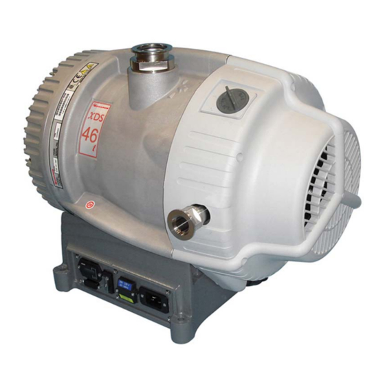
A73101880_F - Introduction Figure 1 General view 1. NW40 inlet port 1. NW40 inlet port 2. Gas ballast control 2. Gas ballast control 3. Cooling fan 3. Cooling fan 4. NW25 exhaust port 4. NW25 exhaust port 5. Fan connector 5. -
Page 12: Gas Ballast Control
A73101880_F - Introduction controlled by an inverter, which manages the supply of current to the motor in accordance with operating conditions, and allows the pump to be connected to a single- phase supply. The voltage changeover switch beneath the voltage changeover switch cover (item 8) must be set to the correct position in accordance with the power supply being used, refer to Connect the pump to the electrical supply on page... -
Page 13: Technical Data
A73101880_F - Technical data 3. Technical data WARNING: If the pump is operated outside the specific limits, the pump housing may become hot. 3.1 Operating and storage conditions Table 1 Operating and storage conditions Ambient temperature range (operation) + 10 °C to + 40 °C Maximum surface temperature of pump body under normal operating conditions and + 40 °C to + 65 °C... -
Page 14: Mechanical Data
A73101880_F - Technical data Sound pressure, measured at ultimate vacuum 55.4 ± 2.5 dB (A) 1 metre from the end of the pump to ISO 3744 and ISO 4871 Vibration: measured at the inlet port (ISO 3744) Class 1C...< 4.5 mm s- (rms) The position of the gas ballast control defines the performance characteristics of the pump. -
Page 15: Electrical Data
A73101880_F - Technical data Inlet connection NW40 Outlet connection NW25 Degree of protection (IEC60529) IP44 3.4 Electrical data Pumps are supplied set to 200 ‑ 230 V. Table 5 Electrical data Supply (V) Phase Frequency (Hz) Current (A) 200 ‑ 230 Single 50 - 60 100 ‑... - Page 16 A73101880_F - Technical data Description Rating Coupler type Item number USA/Canada Plug Type = NEMA, 6‑15P plug (200 ‑ 230 V) Appliance coupler = IEC 60320 style C19 Page 14...
-
Page 17: Installation
A73101880_F - Installation 4. Installation 4.1 Safety WARNING: Obey the safety instructions in this section and take note of appropriate precautions. Failure to observe these instructions may result in injury to people and damage to equipment. WARNING: Do not expose any part of the human body to vacuum as it can cause injury. WARNING: The pump is not recommended for pumping explosive gases or hazardous substances. -
Page 18: System Design Considerations
A73101880_F - Installation ▪ Leak test the system after installation is complete and seal any leaks found to prevent leakage of hazardous substances out of the system and leakage of air into the system. ▪ Mechanical lifting equipment should be attached to the lifting eye on the pump. ▪... -
Page 19: Figure 3 Installation Drawing (Dimensions In Mm)
A73101880_F - Installation Figure 3 Installation drawing (dimensions in mm) Page 17... -
Page 20: Unpack And Inspect
A73101880_F - Installation 4.3 Unpack and inspect WARNING: Use suitable lifting equipment to move the pump. Mechanical equipment should be attached to the lifting eyes, loose slings should not be used. Failure to do so can cause injury to people and damage to the equipment. Refer to Table: General mechanical data on page 12 for the mass of the pump. -
Page 21: Electrical Installation
A73101880_F - Installation 4.5 Electrical installation 4.5.1 Check and configure the pump CAUTION: Isolate the power supply before changing the voltage. Failure to configure the pump electrical supply correctly can result in damage to the pump. Ensure that the voltage shown on the voltage indicator (refer to Figure: General view on page 9) on the motor cover corresponds with the electrical supply voltage. -
Page 22: Leak Test The System
A73101880_F - Installation WARNING: If pumping for a prolonged period above 100 mbar inlet pressure, use an exhaust silencer (refer to Silencer on page 34) or connect to an appropriate exhaust line. Before connecting the pump to the vacuum system, remove the plastic cap from the inlet and exhaust and ensure the inlet strainer is fitted to the pump inlet port. -
Page 23: Operation
A73101880_F - Operation 5. Operation 5.1 Use of gas ballast control (if fitted) The gas ballast control can be used to optimise the performance of the scroll pump for the application. The performance characteristics of the pump with the different ballast settings are shown in Table: Performance characteristics on page 12. -
Page 24: To Achieve Ultimate Vacuum (If Gas Ballast Fitted)
A73101880_F - Operation Switch on the electrical supply to the pump, using the Run/Standby switch Figure: General view on page 9, item 9. With manual operation always use the Run/Standby switch to start/stop the pump. If remote operation is used to control the pump, refer to Remote operation using 15-way D connector on page Open the vacuum system isolation valve (if fitted). -
Page 25: Remote Operation Using 15-Way D Connector
A73101880_F - Operation the process only after any remaining flammable gases or vapours have been purged from the pump and exhaust line. ▪ If liquids that produce flammable vapours could be present in the pump foreline then the inert gas purge to the pump should be left on all the time this liquid is present. -
Page 26: Shut Down
A73101880_F - Operation 5.7 Shut down WARNING: When the pump has been switched off the fan will continue to run for 1 minute. Use the procedure below to shut down the pump: If shutting the pump down prior to a period of storage, remove any process gases by running on high flow gas ballast for at least one hour. -
Page 27: Maintenance
A73101880_F - Maintenance 6. Maintenance 6.1 Safety information WARNING: Obey the safety instructions in this section and take note of appropriate precautions. Failure to observe these instructions may result in injury to people and damage to equipment. WARNING: Wait one minute for capacitor discharge after disconnecting the power supply before working on the pump. -
Page 28: Maintenance Plan
A73101880_F - Maintenance ▪ Do not touch or inhale the thermal breakdown products of fluorinated materials which may be present in the pump if the pump has been heated to 260 °C and above. Fluorinated materials are safe in normal use but can decompose into very dangerous substances (which may include hydrofluoric acid) if they are heated to 260 °C and above. -
Page 29: Inspect And Clean The Gas Ballast Control (If Fitted)
A73101880_F - Maintenance Refit the centring ring and strainer assembly and the O‑ring to the inlet port. Refit the vacuum system to the pump inlet port. Figure 5 Inlet strainer assembly 1. Centring ring and strainer 1. Centring ring and strainer 2. -
Page 30: Clean The External Fan Cover
A73101880_F - Maintenance Figure 6 Gas ballast control assembly 1. Gas ballast control 1. Gas ballast control 2. O‑ring 2. O‑ring 3. Air hole 3. Air hole 4. O‑ring 4. O‑ring 5. Bayonet lugs 5. Bayonet lugs 6. Compression spring 6. - Page 31 A73101880_F - Maintenance Test the earth continuity and the insulation resistance of the pump motor, in accordance with local regulations for the periodic testing of electrical equipment. We recommend that the earth continuity is less than 0.1 W and the insulation resistance is greater than 2 MW.
-
Page 32: Fault Finding
A73101880_F - Fault finding 7. Fault finding 7.1 The pump has failed to start or has stopped ▪ The electrical supply fuse has blown. ▪ The electrical supply voltage does not match that for which the inverter input has been configured. ▪... -
Page 33: The Pump Surface Temperature Is High
A73101880_F - Fault finding 7.4 The pump surface temperature is high ▪ The ambient temperature is too high. ▪ The cooling air supply is insufficient or is too hot. ▪ The process gas is too hot or the maximum continuous operating pressure has been exceeded. -
Page 34: Storage And Disposal
A73101880_F - Storage and disposal 8. Storage and disposal 8.1 Storage Use the following procedure to store the pump: Shut down the pump as described in Shut down on page Disconnect the pump from the electrical supply. Place and secure protective covers over the inlet and outlet ports. Store the pump in cool, dry conditions until required for use. -
Page 35: Service And Spares
A73101880_F - Service and spares 9. Service and spares 9.1 Introduction Our products, spares and accessories are available from our companies in Belgium, Brazil, China, France, Germany, Israel, Italy, Japan, Korea, Singapore, United Kingdom, U.S.A and a world‑wide network of distributors. The majority of these centres employ service engineers who have undergone our comprehensive training courses. -
Page 36: Accessories
A73101880_F - Service and spares Download the latest documents from www.edwardsvacuum.com/HSForms/, follow the procedure in HS1, fill in the electronic HS2 form, print it, sign it, and return the signed copy to us. NOTICE: If we do not receive a completed HS2 form, your equipment cannot be serviced. 9.3 Accessories Note: Accessories could affect the safety of the product. -
Page 37: Tip Seal And Exhaust Service Kit
A73101880_F - Service and spares 9.3.5 Tip seal and exhaust service kit This kit contains all the necessary components to replace the tip seals. Tip seals should be replaced as a pair and only simple tools are required. The kit part number is A73101801. - Page 38 This page has been intentionally left blank.
- Page 39 This page has been intentionally left blank.
- Page 40 edwardsvacuum.com...
Need help?
Do you have a question about the XDS46i and is the answer not in the manual?
Questions and answers