Edwards XDS35i Instruction Manual
Scroll pumps
Hide thumbs
Also See for XDS35i:
- Instruction manual (40 pages) ,
- Instruction manual (40 pages) ,
- Instruction manual (36 pages)
Table of Contents
Advertisement
Quick Links
Description
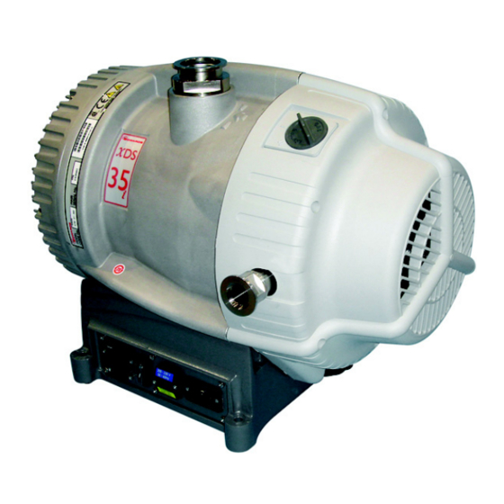
XDS35i Scroll Pump
XDS35iC Scroll Pump
XDS35i Scroll Pump (No Gas Ballast)
Instruction Manual
XDS35i and XDS35iC Scroll Pumps
Electrical Supply
100-120 V, 200-230 V, 50/60 Hz - Set to 200 - 230 V
100-120 V, 200-230 V, 50/60 Hz - Set to 200 - 230 V
100-120 V, 200-230 V, 50/60 Hz - Set to 200 - 230 V
Original Instructions
A730-01-880
Issue J
Item Number
A730-01-983
A730-06-938
A730-05-983
Advertisement
Table of Contents

Related Manuals for Edwards XDS35i


Summary of Contents for Edwards XDS35i
- Page 1 A730-01-983 XDS35iC Scroll Pump 100-120 V, 200-230 V, 50/60 Hz - Set to 200 - 230 V A730-06-938 XDS35i Scroll Pump (No Gas Ballast) 100-120 V, 200-230 V, 50/60 Hz - Set to 200 - 230 V A730-05-983 Original Instructions...
- Page 2 EU authorised to assemble the technical file, that the product(s) XDS35i scroll pump, 100-120 V, 200-230 V, 50/60 Hz, switched to high volts A730-YY-983 XDS35i scroll pump, 100-120 V, 200-230 V, 50/60 Hz, switched to low volts...
- Page 3 P200-10-019 Issue D Material Declaration In accordance with the requirements of the Chinese regulatory requirement on the Management Methods for the Restriction of the Use of Hazardous Substances in Electrical and Electronic Products Order No. 32 (also known as ‘China RoHS2’) and SJ/T 11364 Marking for the Restricted Use of Hazardous Substances in Electronic and Electrical Products: Product Labels Product...
- Page 4 This page has been intentionally left blank.
-
Page 5: Table Of Contents
Clean the external fan cover ..................22 Replace the tip seals ....................22 Test the motor condition ....................23 Fault finding ......................23 © Edwards Limited 2017. All rights reserved. Page i Edwards and the Edwards logo are trademarks of Edwards Limited. - Page 6 Installation drawing (dimensions in mm) ................11 Logic interface schematic .....................18 Inlet strainer assembly ....................21 Gas ballast control assembly ..................22 Page ii © Edwards Limited 2017. All rights reserved. Edwards and the Edwards logo are trademarks of Edwards Limited.
- Page 7 Maintenance plan .......................20 Solenoid operated pipeline valves ................... 28 Associated publications Publication title Publication number Vacuum Pump and Vacuum System Safety P400-40-100 © Edwards Limited 2017. All rights reserved. Page iii Edwards and the Edwards logo are trademarks of Edwards Limited.
- Page 8 A730-01-880 Issue J This page has been intentionally left blank. Page iv © Edwards Limited 2017. All rights reserved. Edwards and the Edwards logo are trademarks of Edwards Limited.
-
Page 9: Introduction
Introduction Scope of this manual This manual provides installation, operation and maintenance instructions for the Edwards XDS35i and XDS35iC scroll pump. The pump must be used as specified in this manual. Read this manual before installing and operating the pump. -
Page 10: Atex Directive Implication
Category 3 is considered appropriate for the avoidance of ignition in the case of a rare malfunction which allows flammable materials or mixtures to pass through the pump whilst within their explosive limits. Page 2 © Edwards Limited 2017. All rights reserved. Edwards and the Edwards logo are trademarks of Edwards Limited. -
Page 11: Description
The XDS is a dry vacuum pump, as all the bearings, with their hydrocarbon lubricant, are isolated from the vacuum space. The pump has an NW40 (item 1) inlet and inlet strainer. © Edwards Limited 2017. All rights reserved. Page 3 Edwards and the Edwards logo are trademarks of Edwards Limited. -
Page 12: Gas Ballast Control
Other materials of construction include fluorocarbon elastomer, nitrile, chemically resistant polymers, nickel, stainless steel and a PTFE composite material. Page 4 © Edwards Limited 2017. All rights reserved. Edwards and the Edwards logo are trademarks of Edwards Limited. -
Page 13: Technical Data
ISO 3744 and ISO 4871 –1 Vibration: measured at the inlet port (ISO 3744) Class 1C…< 4.5 mms (rms) © Edwards Limited 2017. All rights reserved. Page 5 Edwards and the Edwards logo are trademarks of Edwards Limited. -
Page 14: Performance Characteristics
10 degrees Nominal rotational speed 1750 rpm Mass 48 kg Inlet connection NW40 Outlet connection NW25 Degree of protection (IEC60529) IP44 Page 6 © Edwards Limited 2017. All rights reserved. Edwards and the Edwards logo are trademarks of Edwards Limited. -
Page 15: Electrical Data
USA/Canada (200 - 230 V) VW-1 maximum length of 3 metres Plug Type = NEMA, 6-15P plug Appliance Coupler = IEC 60320 style C19 © Edwards Limited 2017. All rights reserved. Page 7 Edwards and the Edwards logo are trademarks of Edwards Limited. - Page 16 A730-01-880 Issue J This page has been intentionally left blank. Page 8 © Edwards Limited 2017. All rights reserved. Edwards and the Edwards logo are trademarks of Edwards Limited.
-
Page 17: Installation
Mechanical lifting equipment should be attached to the lifting eye on the pump. Loose slings should not be used to lift the pump. © Edwards Limited 2017. All rights reserved. Page 9 Edwards and the Edwards logo are trademarks of Edwards Limited. -
Page 18: System Design Considerations
Consider the following points when designing the pumping system: Edwards recommend the use of a foreline vacuum isolation valve to allow the pump to warm up before pumping condensible vapours or if the vacuum needs to be maintained when the pump is not running. -
Page 19: Installation Drawing (Dimensions In Mm)
A730-01-880 Issue J Figure 3 - Installation drawing (dimensions in mm) © Edwards Limited 2017. All rights reserved. Page 11 Edwards and the Edwards logo are trademarks of Edwards Limited. -
Page 20: Unpack And Inspect
Standby switch is accessible. 3.4.1 Mechanical fixing CAUTION Use the four holes located on each corner of the pump base to secure the pump, if required. Edwards recommends the use of M8 bolts. Electrical installation 3.5.1 Check and configure the pump CAUTION Isolate the power supply before changing the voltage. -
Page 21: Connect The Pump To The Electrical Supply
If the pump is operated with the exhaust line blocked, a pressure of 5.5 bar(a) may be generated in the exhaust pipework. Connect the pump using appropriate pipework and fittings. © Edwards Limited 2017. All rights reserved. Page 13 Edwards and the Edwards logo are trademarks of Edwards Limited. -
Page 22: Leak Test The System
Ensure that the sealing surfaces are clean and scratch-free. Edwards recommends the use of an exhaust extraction system suitable for use with all process gases being pumped. Ensure that the exhaust extraction system cannot become blocked or obstructed when the pump is operating. -
Page 23: Operation
4. With manual operation always use the Run/Standby switch to start/stop the pump. If remote operation is used to control the pump, refer to Section 4.6. © Edwards Limited 2017. All rights reserved. Page 15 Edwards and the Edwards logo are trademarks of Edwards Limited. -
Page 24: To Achieve Ultimate Vacuum (If Gas Ballast Fitted)
The inert gas purge flow rate should be continually measured and if the flow rate falls below that required, then the flow of flammable gases or vapours to the pump must be stopped. The Vacuum Pump and Vacuum System Safety publication P400-40-100 is available from Edwards or the supplier. Page 16 ©... -
Page 25: Remote Operation Using 15-Way D Connector
Boost operation is not recommended for the pump as a permanent operation mode, as increased bearing loads will reduce the life of the pump bearings. Please consult Edwards if the boost mode is intended to be used as the limits of operation are application dependent. -
Page 26: Logic Interface Schematic
Link Link open The tolerance of the power supply can be ±10%. Make sure all the unused pins are not connected. Page 18 © Edwards Limited 2017. All rights reserved. Edwards and the Edwards logo are trademarks of Edwards Limited. -
Page 27: Maintenance
Leak test the system after installation is complete and seal any leaks found to prevent leakage of hazardous substances out of the system and leakage of air into the system. Protect sealing faces from damage. © Edwards Limited 2017. All rights reserved. Page 19 Edwards and the Edwards logo are trademarks of Edwards Limited. -
Page 28: Maintenance Plan
(which may include hydrofluoric acid) if they are heated to 260 °C and above. The pump may have overheated if misused or in a fire. Safety Data Sheets for fluorinated materials used in the pump are available on request; contact the supplier or Edwards. Maintenance plan... -
Page 29: Inspect And Clean The Gas Ballast Control (If Fitted)
5. Push the control down as far as it will go and then turn the control clockwise slightly until the bayonet lugs engage correctly. 6. Reset the gas ballast control to the required position. © Edwards Limited 2017. All rights reserved. Page 21 Edwards and the Edwards logo are trademarks of Edwards Limited. -
Page 30: Clean The External Fan Cover
This instruction is applicable to the replacement tip seal kit (contained in minor service kit, refer to Section 7.3.5) that must be fitted. Page 22 © Edwards Limited 2017. All rights reserved. Edwards and the Edwards logo are trademarks of Edwards Limited. -
Page 31: Test The Motor Condition
Test the earth continuity and the insulation resistance of the pump motor, in accordance with local regulations for the periodic testing of electrical equipment. Edwards recommends that the earth continuity is less than 0.1 and the insulation resistance is greater than 2 M. (Reference EN61010-1). -
Page 32: The Pump Is Noisy
There is a leak in the system. The inverter is current limiting the supply. The pump is in idle mode. Page 24 © Edwards Limited 2017. All rights reserved. Edwards and the Edwards logo are trademarks of Edwards Limited. -
Page 33: Storage And Disposal
Dispose of the pump and any components removed from it safely in accordance with all local and national safety and environmental requirements. Take particular care with components and waste oil which have been contaminated with dangerous process substances. © Edwards Limited 2017. All rights reserved. Page 25 Edwards and the Edwards logo are trademarks of Edwards Limited. - Page 34 A730-01-880 Issue J This page has been intentionally left blank. Page 26 © Edwards Limited 2017. All rights reserved. Edwards and the Edwards logo are trademarks of Edwards Limited.
-
Page 35: Service And Spares
Equipment which has been serviced, repaired or rebuilt is returned with a full warranty. The local Service Centre can also provide Edwards engineers to support on-site maintenance, service or repair of the equipment. -
Page 36: Tip Seal And Exhaust Valve Service Kit
This kit contains all the necessary components to replace the tip seal and exhaust valve. Tip seals should be replaced as a pair and only simple tools are required. The kit part number is A730-01-801. Page 28 © Edwards Limited 2017. All rights reserved. Edwards and the Edwards logo are trademarks of Edwards Limited.
Need help?
Do you have a question about the XDS35i and is the answer not in the manual?
Questions and answers