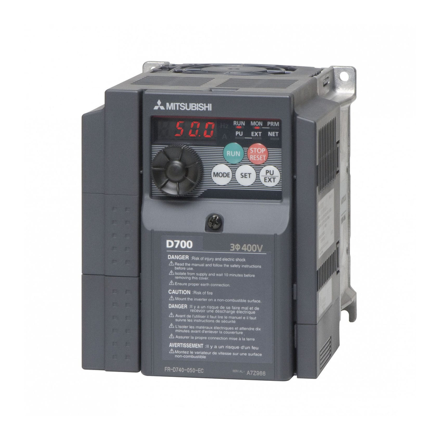
Mitsubishi Electric FR-D700 Instruction Manual
Inverter
Hide thumbs
Also See for FR-D700:
- Instruction manual (290 pages) ,
- Manual (34 pages) ,
- Installation manuallines (28 pages)
Advertisement
Quick Links
INVERTER
FR-D700
Safety stop function instruction manual
CONTENTS
1. General description ............................................................................. 1
2. Installation and wiring ......................................................................... 2
3. Example of safety system configuration ........................................... 5
4. Test and checking failure .................................................................... 9
Advertisement

Related Manuals for Mitsubishi Electric FR-D700


Summary of Contents for Mitsubishi Electric FR-D700
- Page 1 INVERTER FR-D700 Safety stop function instruction manual CONTENTS 1. General description ................1 2. Installation and wiring ................. 2 3. Example of safety system configuration ........... 5 4. Test and checking failure ..............9...
- Page 2 CAUTION The information of this manual is merely a guide for proper installation. Mitsubishi Electric Co. cannot assume responsibility for the compliance or the noncompliance to any code, national, local or otherwise for the proper installation of this equipment. A hazard of personal injury and/or equipment damage exists if codes are ignored during installation.
-
Page 3: General Description
1. General description Features Mitsubishi FR-D700 safety stop function prevents a drive from supplying rotational energy to motors. Dual safety channels ‘S1’ and ‘S2’ cut off the gate-drive power for IGBT to turn off. Input power FR-D700 +24V +24V Internal... -
Page 4: Installation And Wiring
CAUTION The following information is merely a guide for proper installation. Mitsubishi Electric Co. cannot assume responsibility for the compliance or the noncompliance to any code, national, local or otherwise for the proper installation of this equipment. A hazard of personal injury and/or equipment damage exists if codes are ignored during installation. - Page 5 Wiring The safety related terminals are described in Table.2 and Table.3 Table.2 The safety related terminals Terminal Description Rating Symbol For input of safety stop channel1. Input resistance:4.7kΩ S1-SC is Current : 4 to 6 mA Open: In safety stop mode. (In case of shorted to SC) Short: Non safety stop mode.
- Page 6 Table.3 Truth table of Safety related signals Internal safety RUN or A-C Input power S1-SC S2-SC SO (SAFE) Drive state circuit fault (SAFE2) *2 *3 OFF(Open) OFF(Open) Drive shutoff (Safe state) No failure OFF(Open) ON(Close) Drive enable Short Short Detected OFF(Open) OFF(Open) Drive shutoff (Safe state)
-
Page 7: Example Of Safety System Configuration
Safety Circuit MITSUBISHI MELSEC Safety relay module QS90SR2SN-Q FR-D700 Fig.3 Safety system example 1 – STOP asynchronous with emergency stop button and fault detection through A-C output. For safety stop, configure the wiring as shown in Fig.3 above. Note: the above wiring is configured to prevent restart in case of a fault. - Page 8 August 2010 or later for the safety stop function NOTE When using the safety stop function, do not connect the FR-D700 series manufactured in July 2010 or before together with the one manufactured in August 2010 or later. If connected together, the safety stop function may not work properly.
- Page 9 • Example when using multiple FR-D700 inverters manufactured in July 2010 or before A(SAFE2) START STOP STOP IGBTs Emergency stop button SOURCE Gate Gate Driver Driver +24V +24V COM0 COM1 Internal DC24V +24V Safety Circuit MITSUBISHI MELSEC Safety relay module...
- Page 10 Safety Circuit MITSUBISHI MELSEC Safety relay module QS90SR2SN-Q FR-D700 U V W Fig.6 Safety system example 2 – STOP synchronous with emergency stop button and fault detection through RUN output. For safety stop, configure the wiring as shown in Fig.6 above.
-
Page 11: Test And Checking Failure
(3) If there is no different state from Table.5, check the systematic performance, such as, press the Emergency switch, press the start/restart button at the failure detected (RUN-SE opened), and so on. (4) Finally clear the error record of the FR-D700 (see the user manual how to clear the error record). - Page 12 MEMO...
- Page 13 REVISIONS Print Date Manual Number Revision Aug. 2009 BCN-A211508-000-C First edition Change Dec. 2009 BCN-A211508-000-D Example of Safety stop connection Addition Jan. 2010 BCN-A211508-000-E Diode specification for multiple connection Addition Jul. 2010 BCN-A211508-000-F Example of multiple connection BCN-A211508-000-F...
- Page 14 Phone: +380 (0)44 / 494 33 55 Fax: +380 (0)44 / 494-33-66 Mitsubishi Electric Europe B.V. /// FA - European Business Group /// Gothaer Straße 8 /// D-40880 Ratingen /// Germany Tel.: +49(0)2102-4860 /// Fax: +49(0)2102-4861120 /// info@mitsubishi-automation.com /// www.mitsubishi-automation.com...
Need help?
Do you have a question about the FR-D700 and is the answer not in the manual?
Questions and answers