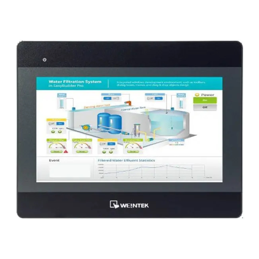
Weintek MT8102iP Series - Touch Panel Manual
- Installation instructions manual (2 pages)
Advertisement
Installation and Startup Guide
This document covers the installation of MT8102iP Series HMI, for the detailed specifications and operation, please refer to Brochure and EasyBuilder Pro User Manual.
Install Environment:
| NEMA Rating | MT8102iP Series HMI is NEMA 4 rated (Indoor Only). |
| Electrical Environment | MT8102iP Series has been tested to conform to European CE requirements. This means that the circuitry is designed to resist the effects of electrical noise. This does not guarantee noise immunity in severe cases. Proper wire routing and grounding will insure proper operation. |
| Environmental Considerations |
|
Unpacking the Unit
Unpack and check the delivery. If damage is found, notify the supplier.
NOTE: Place the operator panel on a stable surface during installation. Dropping it or letting it fall may cause damage.

- Installation Instruction, 2-sided A4 *1
- Human Machine Interface *1
- Power Connector *1
- Brackets & Screws *1 pack
- Fuse 1.6A/250V 5*20mm *1
Installation Instructions


Secure the operator panel in position, using all the fastening holes and the provided brackets and screws. Screw Torque: 2.6 ~ 3.9 lbf.in. (For reaching waterproof effect and preventing the panel from being deformed.)
Power Connections

NOTE:
- Connect positive DC line to the '+' terminal and the DC ground to the '-' terminal.
- When downloading project using a USB cable, do not connect HMI with PLC and PC simultaneously, for electric potential difference may result in damage to HMI or PC.
System Settings
When HMI is powered up and displays image, click the system setting button. (Default System Password: 111111) It is necessary to connect the HMI to your network through a RJ-45 cable.

Go to the Network tab, you may choose to auto get DHCP IP, or designate your own IP.

EasyBuilder Pro Software Settings

Launch EasyBuilder Pro software, select your project file, press F7 shortcut key to open the download dialog box:
Select Ethernet > IP tab > Enter your HMI IP > Click Download to download this project file to HMI.
It is recommended to use screensaver and backlight saver to avoid image persistence caused by displaying the same image on HMI for a long time.
( Please refer to EasyBuilder Pro User Manual for software operation details )
Communication Connections
NOTE:
- COM2 and COM3 RS-485 2W support MPI 187.5K, please use one at a time.
- Only Tx & Rx (no RTS/CTS) may be used for COM1 RS-232 when COM3 RS-232 is also used.

Jumper Settings

| 1-2 | 3-4 | Mode |
| Short | Open | Touch Screen Calibration Mode & Restore Factory Default |
| Open | Short | Boot Loader Mode |
| Open | Open | Normal |
Please prepare a jumper cap for setting the jumpers.
Another way to enter touch screen calibration mode is: Press and hold anywhere on the screen for more than 2 seconds when HMI starts.

NOTE: Make sure that all local and national electrical standards are met when installing the unit. Contact your local authorities to determine which codes apply.
 Power Power | The unit can be powered by DC power only, voltage range: 10.5~28VDC, compatible with most controller DC systems. The power conditioning circuitry inside the unit is accomplished by a switching power supply. The peak starting current can be as high as 2A. |
| Fusing Requirements | If the display does not come on within 5 seconds of power up, remove power. An internal fuse will prevent damage if the polarity of the DC power is incorrect. Check wiring for proper connections and try to power up again. |
| High Voltage | An Internal fuse will prevent damage for overcurrent condition however it isn't guaranteed. DC voltage sources should provide proper isolation from main AC power and similar hazards. |
| Emergency Stop | A Hard-wired EMERGENCY STOP should be fitted in any system using an HMI to comply with ICS Safety Recommendations. |
| Supply Voltage Condition | Do not power the unit and inductive DC loads, or input circuitry to the controller, with the same power supply. Note: The 12 or 24 VDC output from some controllers may not have enough current to power the unit. |
| Wire Routing |
|

| Hardware Considerations | The system designer should be aware that devices in Controller systems could fail and thereby create an unsafe condition. Furthermore, electrical interference in an operator interface can lead to equipment start-up, which could result in property damage and/or physical injury to the operator. If you use any programmable control systems that require an operator, be aware that this potential safety hazard exists and take appropriate precautions. Although the specific design steps depend on your particular application, the following precautions generally apply to installation of solid-state programmable control devices, and conform to the guidelines for installation of Controllers recommended in NEMA ICS 3-304 Control Standards. |
| Programming Considerations | To conform with ICS Safety Recommendations, checks should be placed in the controller to ensure that all writable registers that control critical parts of plant or machinery have limit checks built into the program, with an out-of-limit safe shut down procedure to ensure safety of personnel. |
Documents / ResourcesDownload manual
Here you can download full pdf version of manual, it may contain additional safety instructions, warranty information, FCC rules, etc.
Advertisement


Need help?
Do you have a question about the MT8102iP Series and is the answer not in the manual?
Questions and answers