
Related Manuals for weintek MT-608S


Summary of Contents for weintek MT-608S
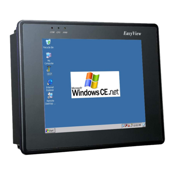
- Page 1 MT-608S RISC-based operator interface terminal with 7.7” flat panel display User’s Manual...
-
Page 2: Table Of Contents
2.3.2 Connector COM2 [RS232] ..............14 2.3.3 Connector COM3[RS485] ..............14 2.3.4 USB Client port...................15 2.3.5 USB Host port..................15 2.3.4 Dip Switch ..................16 2.4 CE Requirements ...................17 2.5 Dimensions of MT-608S................18 Chapter 3 Windows CE.NET ..................20 3.1 Introduction....................20 3.2 Utilities......................20 3.2.1 Soft-Keyboard..................20 3.2.2 System Settings...................21 3.2.3 IPSM ....................24... - Page 3 3.4 Application program development..............29 3.4.1 Microsoft eMbedded Visual C++ 4.0..........29 3.4.2 MT608 SDK..................30...
-
Page 4: Copyright
No part of this manual may be reproduced, copied, translated, or transmitted in any form or by any means without the prior written permission of Weintek Labs., Inc. Information provided in this manual is intended to be accurate and reliable. However, Weintek Labs., Inc. -
Page 5: Safety Instructions
Overview This section states the safety instructions, which must be followed when installing, operating and servicing the MT-608S. If neglected, physical injury and death may follow, or damage may occur to controller and related equipment. The material in this chapter must be studied before attempting any work on, or with, the unit. -
Page 6: Chapter 1 Introduction
Intel™ PXA255 processor, is of low power consumption without sacrificing performance. The MT608S has 10/100Base-T Ethernet port offering good communication ability as the world is webized. Weintek is offering this OI solution in the way that the MT608S is bundled with Windows CE OS. The built-in Windows CE OS platform forms a bridge that lets MT608S be an open HMI solution for system integration. - Page 7 Sound output: 16 bit sound output RTC: Built-in Power input: 24 VDC, 0.5A maximum Dimension (W x H x D): 231 x 176 x 55mm Weight: 1.3kg FUSE BUSSMANN Fast Acting, Glass Tube Rating: 250VAC, 1A Size: 5x20mm LCD Display Display type DSTN color LCD Display size (diagonal) 7.7"...
-
Page 8: Chapter 2 Installation Instructions
Chapter 2 Installation Instructions 2.1 Mounting Instructions 2.1.1 Location Considerations Care should be taken when locating equipment behind the unit to ensure that AC power wiring, PLC output modules, contactors, starters and relays, and any other source of electrical interference are located away from the back of the unit. Particular note should be taken to the position of variable speed drives and switching power supplies. -
Page 9: Environmental Considerations
2.1.3 Environmental Considerations The MT-600 are to be used indoors as built in displays. Make sure that the displays are installed correctly and that the operating limits are followed (See Specifications). Do not operate the unit in areas subject to explosion hazards due to flammable gases, vapors or dusts. -
Page 10: Power Requirements
2.2.1 Power Requirements The MT-600 can be powered by DC power only. The specified Power voltage range is +21 to 25 Volts DC. This insures compatibility with most controller DC systems. The power conditioning circuitry inside the unit is accomplished by a switching power supply. The peak starting current can be as high as 700mA. -
Page 11: Grounding Requirements
FUSE Replacement: The fuse use on MT608 is: BUSSMANN Fast Acting, Glass Tube Rating: 250VAC, 1A Size: 5x20mm Warning: 1. Make sure the power off before replace the fuse. 2. Do not replace the fuse with a different rating fuse. 2.2.2 Grounding Requirements Chassis ground must be used. - Page 12 damage and/or physical injury to the equipment operator. If you, or your company, use any programmable control systems that require an operator or attendant, you should be aware that this potential safety hazard exists and take appropriate precautions. Although the specific design steps depend on your particular application, the following precautions generally apply to installation of solid-state programmable control devices.
-
Page 13: Communications Connections
2.3 Communications Connections The ports as you look at the back of the case, are the ports for connecting to a PLC or some external device (Controller Connectors). Cable Different cables are required for various devices. Requirements Restrict cable length to less than 500’ (150m) for Caution RS485/422 devices and 50’... -
Page 14: Connector Com2 [Rs232]
2.3.2 Connector COM2 [RS232] Pin Designations Pin assignment of the 9 Pin, Male, SUB-D COM2 [RS-232] Port Pin# Symbol Function COM2 [RS-232] Received Data Transmitted Data Signal Ground Ready to send output Clear to send input Pin 1,6,8 is short. 2.3.3 Connector COM3[RS485] Pin Designations Pin assignment of the 9 Pin, Female,... -
Page 15: Usb Client Port
MT608 COM3 [RS-485] connect RS-485 2 wire Device COM3 [RS-485] RS-485 2 wire Device 9P D-SUB Female Data+ Data+ Data- Data- MT608 COM3 [RS-485] connect RS-485 4 wire Device COM3 [RS-485] RS-485 4 wire Device 9P D-SUB Female RS485 Receive RS485 Receive RS485 Transmit RS485 Transmit... -
Page 16: Dip Switch
2.3.4 Dip Switch Pin1 Pin2 Mode OFF OFF Normal ON OFF Touch Screen Calibrate mode OFF ON Boot Loader mode Pin3,4 unused Touch Screen Calibrate mode: In this mode when you power on the MT600, the screen will display a “+” sign at the center of the screen. -
Page 17: Ce Requirements
2.4 CE Requirements EU directives that apply to the MT-600 Series: EMC Directive (89/336/EEC, 92/31/EEC, 93/68/EEC) electromagnetic emissions and immunity Machinery Directive (89/392/EEC, 91/368/EEC, 93/44/EEC, 93/ 68/EEC) machine safety MT600 products will be CE-marked to indicate compliance with the EMC Directive. The MT-600 Series has been designed to operate satisfactorily in electromagnetic noise (immunity) and without emitting high levels of electrical noise into the environment (emission). -
Page 18: Dimensions Of Mt-608S
2.5 Dimensions of MT-608S Front View Side View Bottom View Cutout dimensions: MT-608S: 222mm(8.74”) W x 167mm(6.57”) H... - Page 19 Rear View a. CompactFlash slot h. USB Master b. Sound ports i. Com1[RS232] c. MIC ports j. Com2[RS232] d. Ethernet port (RJ-45) k. Com3[RS485] e. Fuse l. Dip Switch f. Power connector m. Contrast Adjust VR g. USB client...
-
Page 20: Chapter 3 Windows Ce.net
Chapter 3 Windows CE.NET 3.1 Introduction The MT-600 series operator interface terminal is designed to serve on the Windows CE platform. Windows CE .NET is the successor to Windows CE 3.0. Designed from the ground up for the embedded marketplace, Windows CE .NET delivers a robust real-time operating system for rapidly building the next generation of smart mobile and small footprint devices. -
Page 21: System Settings
for users to attach a keyboard to such small machine. Thus, a software keyboard is embedded in the standard Windows CE OS. Upon boot-up, a small keyboard icon will appear on the status bar. Tap this icon by the stylus to activate/hide this Soft-keyboard. 3.2.2 System Settings MT606 provides an integrated utility for users to make basic setting of the machine. - Page 22 Tapping the “Calibrate” button. The screen will display a “+” sign at the center of the screen. Use a stylus or finger to push the center of the “+” until it moves. The “+” moves to upper-left, lower-left, lower-right and upper-right corners.
- Page 23 MAC address The MAC address page the block shows the network MAC address. Save Tap the Save registry button, would save the registry data to the IPSM folder. Next time reboot the MT608S,Windows CE system will use the stored registry data. System version Show current CE image version.
-
Page 24: Ipsm
Change color mode Select the LCD display color. Suggest select the 256 color mode that can improve the performance. USB State Enable/Disable USB Host port. Suggest disable the USB Host port that can improve the performance. From Jan. 2005, the MT608S without USB Host. -
Page 25: Startup
3.2.4 Startup After the system boot up, the startup execution function would automatically perform. This function is useful for control system to do the initialization processes or some other programs. Step1: Create "startup" directory in in "\IPSM\". Step2: Copy executable files or Shortcut to "StartUp" directory which is created in Step 1. - Page 26 To create a new Remote Desktop Connection 1. Open Remote Desktop Connection. 2. In Computer, type the computer name for your computer running Windows XP Professional that has Remote Desktop enabled and for which you have Remote Desktop permissions. 3. Click Connect. The Log On to Windows dialog box appears. 4.
-
Page 27: Mt608S Networking
3.3 MT608S Networking 3.3.1 Networking via Ethernet The MT608S is equipped with a 10/100Base-T Ethernet controller. To utilize it, change the device name when the MT608 is first turned on. Step Click “Start/Settings/Control Panel” Double click “Network and Dial-up Connections” Find the default device name. -
Page 28: Networking Via Usb Client Port
3.3.2 Networking via USB Client Port The MT-608S can use the USB client to USB host cable connect the USB client port of the MT-608S and the USB host port of the host computer as following: Step Make sure the Microsoft ActiveSync... -
Page 29: Web Browser
3.3.3 Web browser The MT-608S built-in Windows CE OS includes Microsoft IESample. It can be used to browse web pages on World Wide Web via LAN or dial-up connection. 3.4 Application program development The MT-608S is bundled with built-in Windows CE operating system. In real applications users need to execute various applications programs on it. - Page 30 96 MB (128 MB recommended) memory for Windows 2000 Professional or Windows XP Professional. 192 MB (256 MB recommended) memory for Windows 2000 Server. CD-ROM drive required VGA or higher-resolution monitor. A Super VGA (800 x 600 or larger) monitor is recommended.
Need help?
Do you have a question about the MT-608S and is the answer not in the manual?
Questions and answers