Table of Contents
Advertisement
Quick Links
1.0 Installation and Startup Guide
0
Install Environment
7
Where
The MT-600/8000 Series is designed for industrial. The temperature range of operating
Used
is from 32 to 113 °F (0 to 45 °C), as majority of industrial environments. It may not be
suitable for using in certain outdoor applications. Please consult the factory for
advised usage in outdoor applications.
NEMA
The MT-600/8000 Series front bezel is NEMA 4 rated. When installed properly in a
Rating
NEMA 4 panel, the NEMA 4 rating of the panel will not be compromised. This means
that fluids will not enter the panel during wash downs.
Electrical
The MT-600/8000 Series has been tested to conform to European CE requirements.
Environment
This means that the circuitry is designed to resist the effects of electrical noise. This
does not guarantee noise immunity in severe cases. Proper wire routing and
grounding will insure proper operation.
Mechanical
Avoid installing units in environments where severe mechanical vibration or shocks
Environment
are present.
2.0 Installation Instructions
1
2.1 Mounting Instructions
4
2.1.1 Location Considerations
8
Care should be taken when locating equipment behind the unit to ensure that AC power wiring, PLC
output modules, contactors, starters and relays, and any other source of electrical interference are located
away from the back of the unit.
Particular note should be taken to the position of variable speed drives and switching power supplies.
Their input and load cables should be screened to a central star earth point.
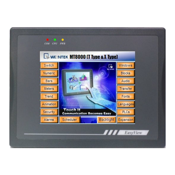
MT-600/8000 series
MT-6056i
Installation Instruction
1
Advertisement
Table of Contents

Related Manuals for weintek MT-6056i


Summary of Contents for weintek MT-6056i
- Page 1 MT-600/8000 series MT-6056i Installation Instruction 1.0 Installation and Startup Guide Install Environment Where The MT-600/8000 Series is designed for industrial. The temperature range of operating Used is from 32 to 113 °F (0 to 45 °C), as majority of industrial environments. It may not be suitable for using in certain outdoor applications.
- Page 2 2.1.2 Making a NEMA-4 Mounting Panel The unit can be mounted into panels with a depth of 4”(105mm). It is recommended that Details the unit be mounted on the front panel of a steel enclosure, through an appropriate opening*. Allow a clearance of 1”(25mm) around the sides of the unit for mounting hardware.
- Page 3 Caution A Hard-wired EMERGENCY STOP should be fitted in any system using an Emergency MT-600/8000 to comply with ICS Safety Recommendations. Stop Caution Do not power the MT-600/8000 and inductive DC loads, or input circuitry Supply Voltage to the controller, with the same power supply. Note: The 24 VDC output Condition from some controllers may not have enough current to power the MT-600/8000.
- Page 4 If you, or your company, use any programmable control systems that require an operator or attendant, you should be aware that this potential safety haza exists and take appropriate precautions. Although the specific design steps depend on your particular application, the following precautions generally apply to installation of solid-state programmable control devices.
- Page 5 1. Using USB cable mini side plug to HMI and another side plug into PC. The PC will display “Found New Hardware Wizard” dialog. Select “Install from a list or specific location (Advanced)”. 2. Check “Include this location in the search”, and assign the path to install Weintek HMI i Series driver from C:\EB8000\usbdriver.
- Page 6 2.3.5 Dip Switch Mode Touch Screen Calibrate mode OFF Hide MT8000 System Setting Bar Boot Loader mode Reserve Normal Touch Screen Calibrate and Reset Password mode: In this mode when you power on the MT8000 series, the screen will display a “+” sign upper-left of the screen.
- Page 7 • EN50082-2 Generic immunity standard, industrial environment Limited Liability Warranty Weintek products include the isolated power supply are covered by a limited liability warranty from fects in material and workmanship. This warranty does not apply : if, in the judgment of Weintek, the product fails due to damage from shipment, handling, storage, accident (natural and man-mad) ;...
- Page 8 4.0 Dimensions of MT-6056i Bottom View Front View Cutout dimensions: MT-6056i 192mm [7.56"] W x 138mm [5.43"] H Rear View a DIP SW & Reset button USB Client port Fuse Com1[RS232] c. Power connector Com1[RS485] VESA 75mm screw holes GME6056I0_MT6056i_Installation_101028...
Need help?
Do you have a question about the MT-6056i and is the answer not in the manual?
Questions and answers