Table of Contents
Advertisement
Quick Links
Description
The 1183 Series wireless heat detectors are used with DMP 1100 Series Wireless Receivers. The 1183 Series is
available in two models: 1183-135F and 1183-135R.
The 1183-135F is a fixed temperature detector that reacts to heat by responding to the fixed 135° temperature
setting. When activated, an alarm is sent to the control panel. The 1183-135F model has a black dot on the heat
collector fin for identification.
The 1183-135R model is a combination rate-of-rise and fixed temperature detector that detects heat quickly by
responding to a rapid temperature increase or a fixed 135° temperature setting. The element responds to a rapid
rise in temperature and sends an alarm to the control panel when the ceiling temperature increases at a minimum
rate of 15°F per minute. An alarm is also sent
to the panel if the ceiling temperature reaches
the fixed 135° setting if the rate-of-rise is not
exceeded.
Compatibility
All DMP 1100 Series Wireless Receivers and Panels
What is Included
The 1183 Wireless Heat Detector package includes
the following items:
•
One 1183-135F Heat Detector with DMP
wireless transmitter installed
OR
•
One 1183-135R Heat Detector with DMP
wireless transmitter installed
AND
•
One 3V lithium CR123A battery
•
Hardware pack
•
Zone name and number label
•
Serial number labels
Transmitter Serial Number
For your convenience, an additional pre-printed serial number label is included. Prior to installing the device,
record the serial number or place the pre-printed serial number label on the panel programming sheet. This number
is required during programming. As needed, use the zone name and number label to identify a specific transmitter.
Programming the Transmitter in the Panel
Locate and record the detector serial number. This number is required during programming. Program the device as
a FIRE type zone in Zone Information during panel programming. At the Serial Number: prompt, enter the eight-
digit serial number. Continue to program the zone as directed in the panel programming guide.
Note: When a receiver is installed, powered up, or the panel is reset, the supervision time for transmitters is reset.
If the receiver has been powered down for more than one hour, wireless transmitters may take up to an additional
hour to send a supervision message unless tripped, tampered, or powered up. This operation extends battery life for
transmitters. A missing message may display on the keypad until the transmitter sends a supervision message.
Transmitted Signal Outputs
The heat detector provides the signals listed in the table:
Heat Collector Fin
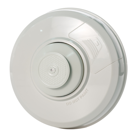
The 1183 Series heat detectors use a heat collector fin (See Figure 1) to detect temperature changes.
The fin is spring loaded and sensitive to handling. Do not set the detector on the collector fin or
put pressure on the fin while handling as this could cause damage to the internal operation.
Inst alla tIon GuIde
1183 Series Wireless Heat Detector
Detector Cover
Detector Cap
Heat
Collector
Fin
Signal
Alarm
Low battery
Detector head removed
Alignment Notch
Test Button
Battery Compartment
Figure 1: Heat Detector Exploded View
Keypad Display
ALARM
LO BAT
TROUBLE
Tamper Post
Mounting Base
Advertisement
Table of Contents

Related Manuals for DMP Electronics 1183-135F


Summary of Contents for DMP Electronics 1183-135F
- Page 1 The 1183-135F is a fixed temperature detector that reacts to heat by responding to the fixed 135° temperature setting. When activated, an alarm is sent to the control panel. The 1183-135F model has a black dot on the heat collector fin for identification.
- Page 2 Selecting the Proper Location (LED Survey Operation) For optimum wireless performance, install the transmitter away from large metal objects. Mounting the transmitter on or near metal surfaces impairs performance. The 1183 Series transmitters provide a survey capability to allow one person to confirm transmitter communication with the receiver. The 1183 transmitter PCB Red Survey LED turns on whenever data is sent to the receiver then immediately turns off when the receiver acknowledgement is received.
- Page 3 Installing or Replacing the Batteries Observe polarity when installing the battery. Use only 3.0V lithium batteries, DMP Model CR123-FIRE or Panasonic Model CR123A. Note: When setting up a wireless system, it is recommended to program zones and connect the receiver before installing batteries in the transmitters.
- Page 4 FCC Information This device complies with Part 15 of the FCC Rules. Operation is subject to the following two conditions: (1) This device may not cause harmful interference, and (2) this device must accept any interference received, including interference that may cause undesired operation. Changes or modifications made by the user and not expressly approved by the party responsible for compliance could void the user’s authority to operate the equipment.
Need help?
Do you have a question about the 1183-135F and is the answer not in the manual?
Questions and answers