Advertisement
Quick Links
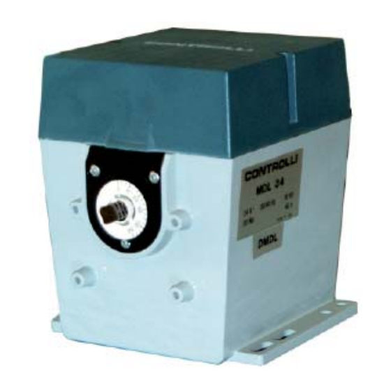
Damper Actuators
Stroking time (s) Torque
Part.
Number
90
(1)
160
MDL22
15
27
MDL24
45
80
MDL26
60
107
MDL62
15
27
MDL64
45
80
MDL66
60
107
MDL42
15
27
MDL44
45
80
MDL46
60
107
MDL32
15
27
MDL34
45
80
MDL36
60
107
MDL52
15
27
MDL54
45
80
MDL56
60
107
(1)
Factory setting.
(2)
The values in brackets indicate the starting torque.
(3)
Models that may be set for voltage or current proportional
control, using the options described further.
(4)
Fixed-range proportional models. This version is physically
obtained by including the MDLS5 module in the MDL3.
series actuator.
APPLICATIONS AND USE
MDL actuators are used in civil and industrial systems for driv-
ing dampers and other devices, which require the control of an
angular position within a max. angle of 160° (e.g. for adjusting
the fl ame in liquid or gas burners).
MDL actuators are equipped with a double shaft output; their
size is such that they are interchangeable with other qualifi ed
manufacturers' actuators. Using the appropriate bracket, they
are also interchangeable with Controlli SL old-model actuators.
MDL actuators can be installed in any position.
Each actuator is available in three basic model types:
− Floating (3p)
− Proportional potentiometric (pot.)
− Proportional voltage or current, with fi xed ranges (prop.)
By means of easily mountable additional modules, the models
with proportional potentiometric control may be voltage or current
controlled in the following versions:
− Selectable fi xed ranges; see MDLS5 option
− Variable range start and slope, see MDLV5 option
2° Emissione
ISO 9001
Power
Control
(2)
Nm
supply
6 (8)
230 V~
3 p
20 (27) 230 V~
3 p
30 (40) 230 V~
3 p
6 (8)
110 V~
3 p
20 (27) 110 V~
3 p
30 (40) 110 V~
3 p
6 (8)
24 V~
3 p
20 (27)
24 V~
3 p
30 (40)
24 V~
3 p
6 (8)
24 V~
pot.
(3)
20 (27)
24 V~
pot.
(3)
30 (40)
24 V~
pot.
(3)
(4)
6 (8)
24 V~
prop.
(4)
20 (27)
24 V~
prop.
30 (40)
24 V~
prop.
(4)
05/12
CONTROLLI S.p.A.
16010 SANT'OLCESE Genova - Italy
Tel.: +39 01073061
E-mail: info@controlli.eu
OPERATION
All models are equipped with a permanent magnet synchronous
motor, which makes stroke time independent from load, and
increases reliability, avoiding the use of mechanical brake. The
stroke angle of the actuator can be adjusted easily by means of
graduated cam disks fi tted internally. On the outside is located
a disk that indicates the angular position of the shaft.
All 24 V~ models have an electrical device for the manual control
in both directions of the actuator in case of absence of control
signal or of failure of the electronic card.
The electric manual control can also be remote, according to the
wiring diagram illustrated in fi g. 5.
It is available an internal mechanism for unlocking the main shaft;
this mechanism permits the shaft to rotate freely in both direc-
tions, simplifying assembly operations and cam calibration.
In the models with fl oating control is available, as an optional
accessory, an auxiliary potentiometer (its card is preset for mount-
ing 1 additional potentiometer, on request). In the models with
proportional control it is also available an output signal depending
on the angular position of the shaft, and a device for reversing
the direction of rotation.
The rotation directions are defi ned as "clockwise" or "coun-
terclockwise", in respect with the position indicator side.
MANUFACTURING CHARACTERISTICS
The actuator does not require any maintenance. It consists of
an aluminium die-cast case and upper cover in thermoplastic
material.
Holes for installation are provided both on the base and on the
front.
The reduction gear has output shaft supported by self-lubricating
bushings. The electronic card is fi tted on top, it can be reached
by removing the cover, also providing an easy access to the
terminals for wiring connections.
1
Fax: +39 0107306870/871
Web: www.controlli.eu
MDL
DBL021e
Advertisement

Related Manuals for Controlli MDL46


Summary of Contents for Controlli MDL46
- Page 1 Using the appropriate bracket, they are also interchangeable with Controlli SL old-model actuators. MDL actuators can be installed in any position. Each actuator is available in three basic model types: MANUFACTURING CHARACTERISTICS −...
- Page 2 “Technical Characteristics” paragraph. In particular, they can be to the desired one (see fi g. 3). connected to CONTROLLI 500 Line, DIGITROLL 4000, 7000, For the 4...20 mA range it is also necessary to position on SW1 Line 200 and 300 controllers.
- Page 3 MDLV5 Option LIMIT OF SHAFT ANGULAR ROTATION The MDLV5 option is preset for voltage control signal. (stroke 90° = factory setting) To select the current range it is necessary to move the two jumpers preset in JMP position to SW1 position and to act on FIG.
- Page 4 OVERALL DIMENSIONS (mm) MDL ACTUATOR DAMPER OPERATING LEVER (MDLA1) DAMPER CONTROL DEVICE (YS7) N4030 N4031 The performances stated in this sheet can be modifi ed without any prior notice due to design improvements 2° Emissione 05/12 DBL021e Automatic control systems for: air conditioning/heating/industrial thermal process.
Need help?
Do you have a question about the MDL46 and is the answer not in the manual?
Questions and answers