Table of Contents
Advertisement
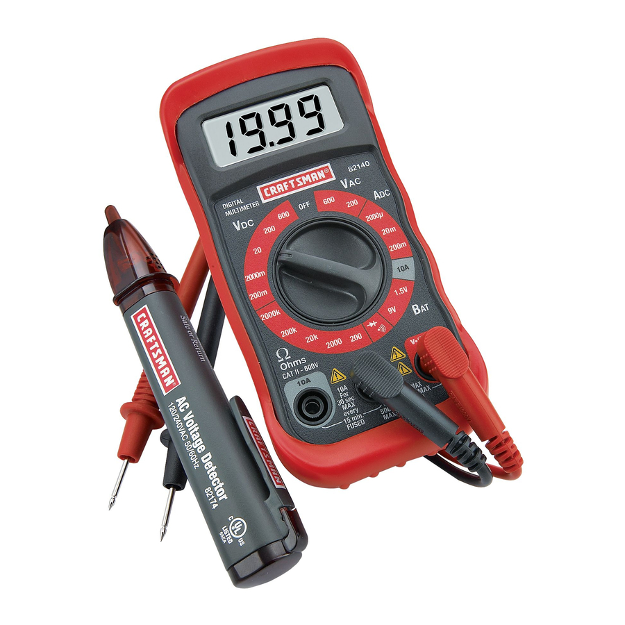
Owner's Manual
Digital MultiMeter
Model No. 82140
and
Voltage Detector
Model No. 82174
CAUTION: Read, understand and
follow Safety Rules and Operating
Instructions in this manual before
using this product.
© Sears, Roebuck and Co., Hoffman Estates, IL 60179 U.S.A.
www.craftsman.com
! Safety
! Operation
! Maintenance
! Español
1
070606
Advertisement
Table of Contents

Related Manuals for Craftsman 82140


Summary of Contents for Craftsman 82140
- Page 1 Owner's Manual Digital MultiMeter Model No. 82140 Voltage Detector Model No. 82174 CAUTION: Read, understand and follow Safety Rules and Operating Instructions in this manual before using this product. © Sears, Roebuck and Co., Hoffman Estates, IL 60179 U.S.A. www.craftsman.com...
-
Page 2: Table Of Contents
TABLE OF CONTENTS Warranty Safety Instructions Safety Symbols Control and Jacks Symbols and Annunciators Specifications Battery Installation Operating Instructions DC Voltage Measurements AC Voltage Measurements DC Current Measurements Resistance Measurements Continuity Check Diode Test Battery Test Maintenance Replacing Batteries Replacing Fuses Troubleshooting Service and Parts Model 82174 instructions... -
Page 3: Warranty
ONE YEAR FULL WARRANTY ON CRAFTSMAN MANUAL RANGING MULTIMETER If this CRAFTSMAN Manual Ranging MultiMeter fails to give complete satisfaction within one year from the date of purchase, RETURN IT TO THE NEAREST SEARS STORE OR OTHER CRAFTSMAN OUTLET IN THE UNITED STATES, and Sears will replace it, free of charge. -
Page 4: Safety Instructions
SAFETY INSTRUCTIONS This meter has been designed for safe use, but must be operated with caution. The rules listed below must be carefully followed for safe operation. NEVER apply voltage or current to the meter that exceeds the specified maximum: Function V DC or V AC mA DC... -
Page 5: Safety Symbols
SAFETY SYMBOLS This symbol adjacent to another symbol, terminal or operating device indicates that the operator must refer to an explanation in the Operating Instructions to avoid personal injury or damage to the meter. This WARNING symbol indicates a potentially WARNING hazardous situation, which if not avoided, could result in death or serious injury. -
Page 6: Control And Jacks
CONTROLS AND JACKS LCD Display Function switch COM jack 10A jack Positive jack Note: Tilt stand, fuse and battery compartment are on rear of unit. SYMBOLS AND ANNUNCIATORS •))) Continuity Diode test " micro (amps) milli ( volts, amps) kilo (ohms) ##$# ohms volts direct current... -
Page 7: Specifications
SPECIFICATIONS Function Range DC Voltage 200mV (V DC) 2000mV 200V 600V AC Voltage 200V (V AC) 600V DC Current 2000"A (A DC) 20mA 200mA Resistance 200$ 2000$ 20k$ 200k$ 2000k$ Battery Test 1.5V NOTE: Accuracy specifications consist of two elements: ! (% reading) –... - Page 8 SPECIFICATIONS Diode Test Continuity Check Battery Test current Input Impedance ACV Bandwidth DCA voltage drop Display Overrange indication Polarity Measurement Rate Low Battery Indication Battery Fuses Operating Temperature Storage Temperature Operating Humidity Storage Humidity Operating Altitude Weight Size Safety Test current of 1mA maximum, open circuit voltage 2.8V DC typical Audible signal will sound if the resistance is less than approximately 30$...
-
Page 9: Battery Installation
BATTERY INSTALLATION WARNING: To avoid electric shock, disconnect the test leads from any source of voltage before removing the battery door. 1. Disconnect the test leads from the meter. 2. Remove the protective rubber holster (if installed). 3. Open the battery door by loosening the screw using a Phillips head screwdriver. -
Page 10: Operating Instructions
OPERATING INSTRUCTIONS WARNING: Risk of electrocution. High-voltage circuits, both AC and DC, are very dangerous and should be measured with great care. 1. ALWAYS turn the function switch to the OFF position when the meter is not in use. 2. If “OL” appears in the display during a measurement, the value exceeds the range you have selected. -
Page 11: Ac Voltage Measurements
AC VOLTAGE MEASUREMENTS WARNING: Risk of Electrocution. The probe tips may not be long enough to contact the live parts inside some 240V outlets for appliances because the contacts are recessed deep in the outlets. As a result, the reading may show 0 volts when the outlet actually has voltage on it. -
Page 12: Dc Current Measurements
DC CURRENT MEASUREMENTS CAUTION: Do not make current measurements on the 10A scale for longer than 30 seconds. Exceeding 30 seconds may cause damage to the meter and/or the test leads. 1. Insert the black test lead banana plug into the negative (COM) jack. -
Page 13: Resistance Measurements
RESISTANCE MEASUREMENTS WARNING: To avoid electric shock, disconnect power to the unit under test and discharge all capacitors before taking any resistance measurements. Remove the batteries and unplug the line cords. 1. Set the function switch to the highest $# position. 2. -
Page 14: Diode Test
DIODE TEST 1. Insert the black test lead banana plug into the negative COM jack and the red test lead banana plug into the positive diode jack. 2. Turn the rotary switch to the 3. Touch the test probes to the diode under test. Forward voltage will indicate 400 to 700mV. -
Page 15: Maintenance
MAINTENANCE WARNING: To avoid electric shock, disconnect the test leads from any source of voltage before removing the back cover or the battery or fuse doors. WARNING: To avoid electric shock, do not operate your meter until the battery and fuse doors are in place and fastened securely. This MultiMeter is designed to provide years of dependable service, if the following care instructions are performed: 1. -
Page 16: Replacing Batteries
REPLACING THE BATTERIES WARNING: To avoid electric shock, disconnect the test leads from any source of voltage before removing the battery door. 1. When the batteries become exhausted or drop below the operating voltage, “BAT” will appear in the right-hand side of the LCD display. The batteries should be replaced. -
Page 17: Troubleshooting
2. Call our Customer Service Line 1-888-326-1006. SERVICE AND PARTS Item Number 82374 93894 82378 82140-DB 82140-DF 82140-CS For replacement parts shipped directly to your home Call 9 am – 5 pm Eastern Time, M - F Description Fuse kit... -
Page 18: Model 82174 Instructions
TO THE NEAREST SEARS STORE OR OTHER CRAFTSMAN OUTLET IN THE UNITED STATES, and Sears will replace it, free of charge. If this CRAFTSMAN Voltage Detector is used for commercial or rental purposes, this warranty applies for 90 days from the date of purchase. - Page 19 WARNING: USE EXTREME CAUTION IN THE USE OF THIS DEVICE. Improper use of this device can result in injury or death. Follow all safeguards suggested in this manual in addition to the normal safety precautions used in working with electrical circuits. DO NOT service this device if you are not qualified to do so.
- Page 20 SPECIFICATIONS Voltage Sensitivity Frequency Detection distance Over voltage Operating Temperature Storage Temperature Humidity Altitude Battery Dimensions/Weight Safety BATTERY INSTALLATION 6. Open the battery door (end cap) by gently prying up/out at the pocket clip using a small screwdriver. 7. Insert two AAA batteries (observe polarity). 8.
-
Page 21: Ac Voltage Detection
WARNING: To avoid electric shock, do not operate the meter until the battery cover is in place and fastened securely. OPERATING INSTRUCTIONS WARNING: Risk of Electrocution. High-voltage circuits, both AC and DC, are very dangerous and should be measured with great care. AC VOLTAGE DETECTION WARNING: Risk of Electrocution.
Need help?
Do you have a question about the 82140 and is the answer not in the manual?
Questions and answers
what fuses does it take
The compatible fuses for Craftsman part number 82140 are:
- 0.2A/250V fast blow fuse for the 200mA range
- 10A/250V fast blow fuse for the 10A range
This answer is automatically generated