Table of Contents
Advertisement
IIIIIIIII
I
2-170701
I
[11 II
........
I II
II
-
--_
l
Sears
k
.............
.
......
owners
manual
MODEL
NO.
161.210400
Caution:
Read Rules For
Safe Operation
and Complete
Operating Test
Procedures
Carefully
............
•........
. .....
PRINTED iN U.S.A.
.;_(/
)-
CRRFTSHRN
ENGINE ANALYZER
FOR 12& 24 VOLT SYSTEMS
. OPERATING INSTRUCTIONS
• SAFETY
RULES
• TUNE- UP PROCEDURES
• REPAIR PARTS
,,
,,,,
,
,,
,,,,,,
,
,I
..........
'
I I
II
Illl
11 IIIIIII
IIII
11
SEARS, ROEBUCK
AND CO. U.S.A.
CHICAGO,
ILLINOIS
6068.4
......
2-17070_
Advertisement
Table of Contents

Related Manuals for Craftsman 161.210400


Summary of Contents for Craftsman 161.210400
- Page 1 2-170701 IIIIIIIII [11 II ..I II Sears .;_(/ ....owners manual MODEL 161.210400 CRRFTSHRN ENGINE ANALYZER FOR 12& 24 VOLT SYSTEMS Caution: . OPERATING INSTRUCTIONS Read Rules For Safe Operation • SAFETY RULES and Complete Operating Test • TUNE- UP PROCEDURES Procedures Carefully •...
- Page 2 TOT Numld 34€-*Lo_ v_XAG[ OnOP T(STS ........ TEST lll!lii(l _I_--E|SStOII COtI_O. $#;1_ TIE.los ..... T[S? _UHO_X !£ST llli_l HF-_ illIIlllNGS ........?_ST liilli_l Wlli!lOi lffN'OtTil IIlD ......lii--l[Ai TEst m, ilIl _4B--ELEC?NICAL iIRIN_ltARNE$S ......TEST _U_ER tEPt.ACfi,I_ e,',_T_ LIST ..........R(ILAc[,MENI...
- Page 3 IMPORTANT will The information in thls manual serve as a generaJ gulde for engine tune-up and charging system tests and adlustments. CONSULT THE VEHICLE SERVICE MANUAL FOR SPECIFIC TUNE..UP INFORMATION TEST PROCEDURES. ALWAYS FOLLOW MANUFACTURER°S SPECIFICATIONS AND TEST PROCEDURES FOR ADJUSTING DWELL ANGLEe IDLE SPEED AND CHARGING...
- Page 4 Wage RULES FOR SAFE AUTOMOTIVE TESTING READ CAREFULLY Read this Owner's Manual and these comportment€ontaining charging bat.. terles should be well ventilated to Rules for Safe Automotive Testing core- prevent accumulaHon of explosive fully. Fa_iure to Follow instructions gases. To avoid spark_, do ru_tdisturb and safety _ies could result tn serious the battery charger connectlonswhile...
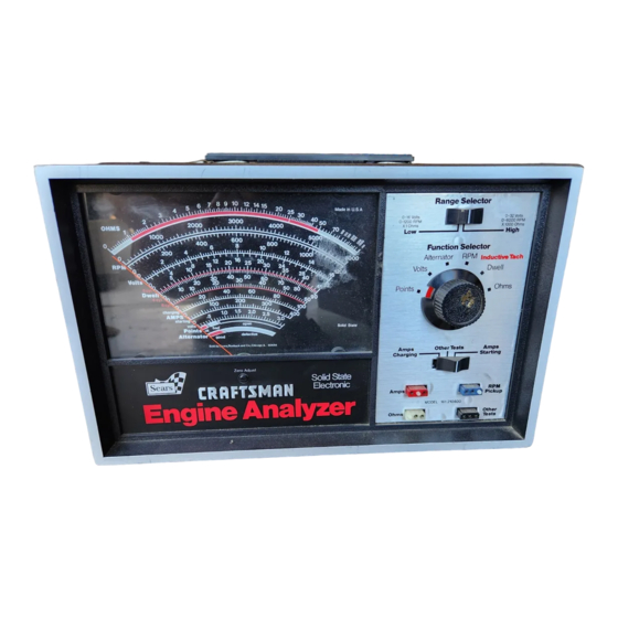
- Page 5 DESCRIPTION FRONT PANEL AND CONTROLS FIGURE I BLACK - OTHER TESTS SOCKET. In- METER. Provides following scales- I • sert BLACK plug on test lead. Low Ohms X 1, 0 to 1,000 Ohms (10 Ohms center scale), HI Ohms X 1,000, (10,000 Ohms center scale)t RPM Hi 0-6000,...
- Page 6 Function Selector Alternator RPM InducttveTach Volts__, well Points m _ Ohms FUNCTION SELECTOR SWITCH POSITIONS FIGURE RPM. Provides i200 or 6000 POINTS. Volt Lo scale-provldes engine speed reading. See item point condition on scale. Also used Page 3. Use Lo-i200 RPM range for locating voltage...
- Page 7 IGNITION ACCESSORIES FIGURE 3 FOREIGN SPARK PLUG ADAPTER. BATTERY POST ADAPTER. Used in Used to make ignition cable tests. electrical systems tests with i00 Amp and 400 Amp shunts. G.M. DIAGNOSTIC CONNECTOR. ADAPTER. Used to make tests on SIDE MOUNT ADAPTER.
- Page 8 v_,a_,.,/l_ll_lr'1_,. I IUI_I_'.'_ r-t_l_C.lll_iL I r..,.._ t O BREAKER POINT CONVENTIONAL IGNITION SYSTEMS METER ZERO ADJUSTER. Before con- Connect the GREEN clip to the dis,. tr_butor termlnai on call primary. necting test leads, always check meter po_nter zero position, if not Attach RPM induction pickup...
- Page 9 CONNECTIONS FOR ENGINE TESTS ELECTRONIC IGNITION SYSTEMS Proceed with tests as outlined in this Connect test leads as instructed manual--Oral fling those tests which previous page for BREAKER POINT apply only to BREAKERPOINT SYSTEMS systemsand as illustrated below with the following exception; See Test Number 15 far proper connection of the GREEN clip.
- Page 10 Test Number 1--Startin_ Crank ing_Vg.!tage, Place function switch in the VOLTS position. Engine must be disabled to prevent Starting for this test. On ELECTRONIC IGNITION, disconnect battery cable at coil or unplug pickup coil connector at distributor or ground HT secondary lead on any external coil system.
- Page 11 Page 9 CLOSE STARTER SHUNT BLACK STARTER AMPS OPEN CHARGING AMPS TO GROUND ON ENGINE NUTS MUST BE TIGHTENED WITH STARTERAMPS A WRENCH. TIGH! THIS SCREW .,c_it_h Po_Z_Zon S_t_ C_r{nt STARTERAND ALTERNATOR FIGURE 10 Conn_c_on_ For S_J_uzt_.ng il C, h o_rg_ng CuArent Measurements FIGURE g Test...
- Page 12 Remove and clean battery terminals and cable terminals in a warm water solution with baking soda to dissolve corrosion, Tighten nuts on starter solenoid terminals. Readings below B volts at the starter usually indicate a defective starter cable or burned solenoid con- tacts.
- Page 13 Page 11 DEFECT ACTION High resistance in the ground Clean and tighten all ground circuit connections Regulator set too high Adjust to the proper setting (If adjustment is possible) Most late model vehicles use a regulator which is of solid state design and cannot be adjusted.
- Page 14 Page 12 IIATTERY _ft AOAPTI[R CONN- tCtlONS ItOlt ALTERNATOR Tilt FIGURE 14 CHARGING ot_,r_ AM ,s gill FIGURE NOTE: If the AMPS indicates below zero (left) during CHARGING STARTING, reverse the leads as shown, FIGURE Caution: DO NOT pull on the wires, necessary_ grasp the terminal...
- Page 15 i'_e "B" CIRCUIT ( External Voltage Regulator) FIGURE 18 ............ II II]llllllnll I IIIIIIIIII II ....On some vehicles if may be inc_onvenlent to connect iumper wlre at the alternator. Battery Jumper Term _nol Im such a iftuaHon remove the regulator con- nector from the voltage regulator and €onnect a iumper wire as illustrated.
- Page 16 ru_E Be sure the shunts are tightly secured to the Battery Amps Adaptor as shown in Key No. I Page 5 , and the Function Selector Switch is placed in the Alternator position. CAUTION: TIGHTEN ALL NUTS ON THE BATTERY ADAPTOR WITH A WRENCH TO AVOID EXCESSIVE HEAT AND POSSIBLE SHUNT DAMAGE.
- Page 17 Page 15 With the engine running, carefully open the starter shunt as shown in Key 10 on page Observe the current (amps) reading on the 0-100 Amps scale, reduce engine speed to curb idle and compare meter reading with the manufacturer's specifications.
- Page 18 Page 16 Test Number 9--Ohms Test The ohmmeter test is powered by an internal 9 volt battery. zero calibration required by the operator. Place Function Selector Switch in the Ohms position and select either the Hi or Lo range to match the component under test.
- Page 19 Page 17 BATTERY REPLACEMENT. When the g volt battery is low, the meter will not read full scale with the clips open. Replace the battery to obtain accurate OHMS measurement. IMPORTANT: When the tester is not in use or when Ohms tests are completed ALWAYS turn the Function Selector Switch OUT of the Ohms position to prevent battery discharge.
- Page 20 (+) or Battery (Bat) terminal of the Ignition Coil. VOLTAGE AT THIS POINT RESULTS IN A "NO START" CONDITION, Perform this test as follows: Place the Function Selector Switch of your Craftsman Analyzer in the VOLTS position. Place the RANGE SELECTOR in the 0-16 volts position.
- Page 21 Page 1_ Turn the vehicle's Ignition Switch (key) to the "ON" or "RUN" position only. Do not start the engine. Read the analyzer's voltmeter. Normal readings should be as follows: Breaker Point Systems: At or slightly below battery voltage (12 volts) if the points are open.
- Page 22 Page 20 Test Number 12--Breaker Point Resistance NOTE; This test does not apply to Electronic ignition systems. NOTE: Remove the distributor cap before testing and inspect the contact points. If they are blued, blackened, or noticeably pitted, they should be replaced. Normal, used contact points are light gray In color.
- Page 23 Page 21 T.estNumber 13--Dwell Adjustment--Breaker Point S#s##m.s Rotate the Function Selector Switch to the dwell position. Consult your vehicle service manual to determine which vacuum hoses, if any, should be disconnected and plugged prior to making dwell ad- justment or test. Run the engine at specified idle speed and note dwell reading on proper 4-6 or 8-cylinder scale to correspond to the engine under test.
- Page 24 Page Z2 NOTE: Disconnect omd plug the vacuum advance llne from the disfr;butor. If the vehicle is equipped with an advance-retard sole- t_o;d, disconnecf the wire at the carburetor WINDOW end, 1/8" ALLEN WRENCH ADJUSTMENT SCREW GM TYPE PLUG END OF VACUUM LINE FIGURE 23 FIGURE 24...
- Page 25 Page 23 NOTE; It is important to recheck the ignition timing every time the dwell is adjusted. A one degree change in dwell causes a one degree change in timing. THIS TEST DOES NOT APPLY TO ELECTRONIC OR TRANSISTOR IGNITION SYSTEMS EXCEPT DELCO HEI AND THOSE TYPES USING CONVENTIONAL CONTACT POINTS.
- Page 26 T_estNumbeF !4-_DwelI Variation Test Repeat Test Number 13, Steps i-4 NOTE: This test does not apply to transistorized ignition systems (except those types using conventional contact points). Rotate the Function Selector Switch to the DWELL position. Disconnect and plug vacuum advance hose(s) as described in DWELL Angle Test 13 on page 21 and 2_ Operate engine at curb idle.
- Page 27 Ford-- On Ford cars with 1974 electronic ignition systems, use the Ford adapter pin as shown in Figure29, below. Connect the GREEN clip from the Craftsman Engine Analyzer to the adapter pin. Connect the RED cllp to the positive battery terminal and the BLACK clip to a clean and secure ground such as the engine block.
- Page 28 Zb On 1975 and later Ford electronic ignition systems, connect the GREEN cllp from the Craftsman Engine Analyzer to the wire terminal on the TACH side of the coll as shown in FIGURE 3_ below. Connect the RED clip to the positive battery terminal and the BLACK cllp...
- Page 29 On the General Motors integral ignition coil, V-8 and V-6 HEI systems, slide the adapter onto the TACH terminal as shown in Flgure 33 below. Connect the GREEN clip from the Craftsman Engine Analyzer to the adapter just installed. Connect the RED cllp to the positive battery termlnal and the BLACK clip to a clean and secure ground such as the engine block.
- Page 30 Page 28 Ford / Chrysler / American Motors i. Connect the test leads from the Craftsman Engine Analyzer as shown in Figure 29or 30 as appropriate to the vehicle under test. Keep the leads clear of fan, belts, and pulleys.
- Page 31 , use TestNumberi6--initia] ignition Timing This test should be made following any dwell adjustments as the point setting controls the basic ignition timing. On electronic ignition systems refer to the vehicle service manual for special instruction_. Spark timing controls are used to advance or retard timing. Follow manufacturer's service procedures to check &...
- Page 32 Hold down BATTERY POST ADAPTER CONN- screw or bolt ECTIONS FOR STARTING ENGINE FIGURE 37 ROTATION FIGURE 34 ......' ....II1[I fl[ [[[[ [[[[I J[lll i rrrlll Vehicle Battery ROTATION'\II 1[Ii_"_ _/ Tester PlckuI FIGURE 35 .., ............11111111 hill I[IH[...
- Page 33 Many of today's modern vehicles use sophisticated computer controlled spark advance systems. Your Craftsman Analyzer, a top quality timing light such as the Sears 213400 Timing Light or 219400 Advance Timing Light, and the vehicle service manual are essentialitools for accurately checking these complex advance systems.
- Page 34 Page 3Z Test Number IB--Carburetor Adjustmentr-M_xture (Atr_Fue!_Ratia_ Rotate the Function Selector Switch to the RPM position. Slide the Range switch to the L0-1200 RPM position for idle speed tests. EMISSION CONTROL SYSTEMS, Carburetors on late-model vehicles usually have sealing caps on idle mixture screws which prohibit or restrict carburetor adjustment.
- Page 35 By using the RPM, VOLTS, and OHMMETER sections of your Craftsman Analyzer and specific tests described in your vehicle service manual, you will be able to diagnose faults and properly adjust the antl-dleseling solenoid.
- Page 36 Page 34 Test Number 21 and 22-_Fast !dle and Automatic Choke Adjustment The purpose of the fast idle function is to maintain proper engine speed during cold engine and warm-up operation. Additional throttle opening is needed with the automatic choke butterfly valve in a closed or partially closed position to keep the engine running smoothly and prevent stalling.
- Page 37 D=._ 35 Test Number 23--Ignition Coil Refer to Test Number 9--OhmsTest (sections I-7) for Ohmmeter use. IGNITION COIL PRIMARY RESISTANCE TEST Set the Range Slide Switch to the OHMS X I position. Remove the primary wires from both coil terminals. Connect the RED and BLACK test leads to primary coil terminals, as illustrated in Figure 42.
- Page 38 COILSECONDARY RESISTANCE ONOHMS X 1000 POSITION FIGURE 43 Remove the high tension lead from the coil tower, Be sure the ignition switch is OFF. Connect one of the OHMMETER test leads to either coil screw terminal. (On late model Ford cars, use the Ford Adapter as illustrated on page 25.) Connect the other lead to a spark plug adapter and insert in the coil tower as shown, Read the Ohms X 1000 scale on the meter and compare the reading with...
- Page 39 DO NOT yank on the cable to remove it. Use the X 1000 position on the RANGE SELECTOR of the Craftsman Analyzer. Connect the RED and BLACK Ohn=netertest leads to the ends of the cable as shown below, and use an adaptor spring at the SPARK PLUG END of the cable as shown.(Figure 44_...
- Page 40 Page38 Te__..t. N umbe.r..2 5._.Ba.]]. as t, ..Res .!s to r Refer to Test Number 9--Ohms Test (sections 1-7) for Ohmmeter use. The purpose of the ballast resistor (when equipped) is to limit the current available to the ignition coil when the vehicle is running. Failure of this resistor results in a dead engine.
- Page 41 Test Number 26--lqnition Switch The ignition switch performs many duties beyond starting the vehicle. With the guidance of your vehicle service manual, your Craftsman Voltmeter and/or Ohmmeter can confirm operation of the ignition switch, Some of the ignition switch functions are as follows:...
- Page 42 Page 40 ELECTRONIC IGNITION SYSTEMS The following ten pages are devoted to the four basic Electronic Ignition Systems as used by American Motors, Chrysler Corporation, Ford Motor Company, and General Motors, The diagrams and charts will step you through point-to-point testing of the various components within each system.
- Page 43 Page 41 GENERAL MOTORS HIGH ENERGY IGNITION-- DISABLING PROCEDURES When performing Charging System teals on General Motors vehicles equipped with High Energy Ignition (HEt), the engine can be prevented from starling as follows: ..i II .,r r, ,, .,,i,rbl Ir I, , ,, J,im.,.I,,,, ,,,, ,,,,,,,,, SYSTEMS WITH COIL IN DISTRIBUTOR Disconnect primary wire from...
- Page 44 Page 42 ,Tes_t N umber 27 ELECTRONIC HIGH TENSION MODt LE ITPUT TERMINAL POS,-,,_ COIL TERMINAL COIL GROUND TERMINAL IGNITION SWITCH BLACK COIL NEG4 12 VOLT BATTERY DISTRIBUTOR CONNECTOR DISTRIBUTOR SENSOR UNIT DISTRIBUTOR GROUND FIGURE 46 AMERICAN MOTORS ELECTRONIC IGNITION SYSTEM...
- Page 45 Page 43 Number Continued AMERICAN MOTORS ELECTRONIC IGNITION COMPONENTS _,s ¸ - =±- , ,,111 ......:........S[LECTOR C LIP firST TESt KNOB CONNECTIONS PROCEDURE POSITION BLACK RESULTS Remove Coil High Tension W_re from the distributor and Battery Batte,y ground _t. Crank Engine.
- Page 46 Page 44 IGNITION SWITCH I2 V, BATTERY GROUND COMP. RESISTOR NOTE LOCATION SIDE DUAL BALL._ST AUXI LIARY RESISTOR SIDE ELECTRONIC CONTROL UNIT COIL FIGURE ISTRIB!. DISTRIBUTOR CONNECTOR CHRYSLER ELECTRONIC IGNITION SYSTEM...
- Page 47 CHRYSLER ELECTRONIC IGNITION COMPONENTS SELECTOR CLIP CONNECTIONS TEST PROCEOURE TEST KNOB PQS_TION BLACK RESULTS RemQve the High Tet_slor_ Wire from the dls.ttibutor and Battery StcJ_'e grouttd it. Crank Engine, The meter should read at iea_t of Charge 16 VOLTS Battery 8ah'et-y 9 ruffs while cranking.
- Page 48 Page 4(_O1L CONNECTOR YELLOW TO "DEC" TERMINAL (DISTRIBUTOR ELEC- TRONIC CONTROL IGNITION SWITCH 12 V.BATTERY GROUND D.E,C. MODULE TO "BAT" TERMINAL DISTRIBUTOR GROUND BLADES SOCKETS FIGURE 48 ORA I( ORANGE BLUE/ _OWN BLACK BLACK FORD ELECTRONIC * inspect Harne_s Connectors for white &...
- Page 49 Test Number 29 Continued FORD ELECTRONIC IGNITION COMPONENTS CLIP SELECTOR TEST PROCEDURE T{ST CONNECTIONS KNOB RESULTS POSITION I BLACK Remove Call High Tensiot_ Wire from the dlstr_butor and Battery State ground it. Crank E_gtne, Meter should read at least 16 VOLTS Battery Battery of Charge...
- Page 50 Page 48 Test Number DISTRIBUTOR PINK LEAD IGNITION SWITCH HiGH TENSION POS. OUTPUT CONDENSER IS USED ONLY NEG. RADIO INTERFERENCE SUPRESSION 12 V BATTERY ALL INVOLVED IN IGNITIOI" PERFORMANCE. BROWN GROUND LOWER HOUSING "WHITE -PiCK-UP HARNESS LEADS ELECTRONIC DISTRIBUTOR WiTH CAP MODULE ROTOR REMOVED.
- Page 51 • _w. -t,_ _S!: Number _3Q,,Continued DELCO HEI IGNITION COMPONENTS-SYSTEMS WITH COIL IN DISTRIBUTOR S LECTC ......TESTPROCEOURE TEST KNOll CONNECTIONS Remove Pink Lead 4 from Dhtrlbutot Cop end crank A flattery State J_ttery Battery e_gtne, Meter should_ead at least9,6 vghs.lf lawe_, of Charge 16 VOLTS Pro,(÷)
- Page 52 Page 50 Test Number 31 IGNITION SWITCH IGNITION SWITCH FEED TERMINAL POS. COiL CONNECTOR 'HIGH TENSION OUTPUT TERMINAL HOUSING HARNESS GROUND CONDENSER iS USED ONLY FOR RADIO INTERFERENCE FIGURE 50 SUPRESSiON AND NOT ALL INVOD/ED IN IGNITION PERFORMANCE. DELCO HEI IGNITION SYSTEM WiTH SEPARATE...
- Page 53 Test Number 31 Continued rage DELCO HEi IGNITION COMPONENTS-SYSTEMS WITH SEPARATE COIL ...., 1 ..CLIP SELEC TaR PROCEDUR_ TEST TEST CONNECTIONS KNOB RESULTS POSITION BLACK Remove Ignition Swift_h Feed Terminal from Coil and crank Battery State of 16 VOLTS l_ttery Battery engine.
- Page 54 DWELL-TYPE voltage from the EleCtronic Control Module (ECM) to maintain this air-fuel ratio under widely varying driving conditions. The Craftsman Engine Analyzer can be used to check this voltage by reading the six-cylinder DWELL scale, 0-60°, and by performing the procedure in this section.
- Page 55 Page ENGINE CONDITION DWELLMETER READINGS Start Mode (cranking) Warm engine operation at idle Constantly varying between or part-throttle with constant i0_ and 50_ (Higher engine engine speed. See Note Below. speeds result in faster variations.) Acceleration and deceleration Constantly varylng between (changing engine speed) 10_ and 50°...
- Page 56 Page 54 Insert the BLACK test lead p]ug into the BLACK "OTHER TESTS,' socket. Connect the BLACK clip to a clean connection on the engine block and the GREEN cllp to a clean connection on the car body. Scrape away grease or paint, if necessary, to make a good metal-to-metal connection.
- Page 57 vage Test Number 34A--Puse Tests Automotive fuses can be tested as follows: Connect the BLACK clip from the analyzer's voltmeter lead to a good ground on the engine or car body. Turn the Function Selector Switch to the VOLTS position. Insert the BLACK plug into the BLACK OTHER TESTS socket.
- Page 58 Paqe 56 Test Number 34B--Horn Set the Function Selector Switch to the VOLTS position, Using the ALL OTHER TESTS leads, connect RED lead to the terminal of the horn relay that connects to the horns and BLACK lead to a good ground as shown in Figure 57.
- Page 59 Page Test Number 34C--Low Volt.ageIJropTests in addition to the POINT RESISTANCE test described on page 20, this position can be used to test the vehicle's electrical system for low voltage drops. Set the Function Selector Knob to the POINTS LOW VOLTS position.
- Page 60 Your vehicle service manual will specify what resistance in ohms should be present across the various motor leads. These values will typically be low in value, hence the X i position of the Craftsman Analyzer Range Selector should be used,...
- Page 61 The end result of this is that one or more electrically oper- ated devices in the vehicle will not operate as they should. By using your Craftsman Analyzer, Voltmeter, Ohmmeter, and Points (Low Voltmeter) functions, and with the guidance of your service manual you can correct certain harness defects.
- Page 62 lulul)C_i(_..¸ ,Ji-...
- Page 63 TABLE i Key No. Part No. DescHptlon 290-102 Nut s 3/8-32 450-132 Knob, Selector 210-105 Washer, Flat 3/8 450-130 Glamor Cap STD610605 Screwe Self Tap #6 x i/2 Lg. 400-290 Rest Pad (2) 180-740 Cases Bottom and Back 1000-752 Case_ Top Assembly 180-739 Case, Baffle 400-467...
- Page 64 Ir M. r lint I nl ........ ENGINE owners manual ANALYZER Now that you have purchased your CRAFTSMAN ENGINE ANALYZER_ should a need ever exist for repair parts or service, simply contact Sears, Roebuck and Co, stores. Be sure to pro-...
Need help?
Do you have a question about the 161.210400 and is the answer not in the manual?
Questions and answers