Table of Contents
Advertisement
Quick Links
Advertisement
Table of Contents

Related Manuals for Getinge Maquet PowerLED II 700


Summary of Contents for Getinge Maquet PowerLED II 700
- Page 1 Maintenance Manual Maquet Rolite NM 01833 EN 03 2022-09-19...
- Page 2 Copyright All rights reserved. This document may not be copied, adapted or translated without prior written permission, except as permitted under copyright law. © Copyright 2021 Maquet SAS Subject to technical changes. The illustrations and technical specifications provided in this manual may, on account of future product devel- opments, differ slightly from the actual product supplied.
-
Page 3: Table Of Contents
Contents Contents Introduction ......................Preface ..............................Other documents relating to this product....................Information about this document ......................1.3.1 Abbreviations ......................... 1.3.2 Symbols used in this manual ....................1.3.2.1 Cross-references....................1.3.2.2 Reference numbers..................... 1.3.2.3 Actions and results ....................1.3.2.4 Menus and buttons....................1.3.3 Definitions .......................... - Page 4 Contents 4.3.3.1 Screen brightness ....................25 4.3.3.2 Date and time ...................... 26 4.3.3.3 Information ......................27 4.3.3.4 Restarting the touchscreen control panel............28 4.3.3.5 Maintenance......................29 4.3.3.6 Resetting and restarting the touchscreen control panel ........30 4.3.4 Conducting backup tests......................32 4.3.4.1 From the touchscreen control panel..............
-
Page 5: Introduction
Given the confidential nature of the information in this document, it is distributed exclusively to customers and installers of Maquet SAS products. • Make sure that you have the latest versions of these documents. Check with our Getinge net- work to confirm that it is the case. •... -
Page 6: Information About This Document
Introduction Information about this document Information about this document 1.3.1 Abbreviations Volista Access Volista StandOP AIM* Automatic Illumination Management Electromagnetic compatibility FSP* Flux Stability Program LMD* Luminance Management Device High Definition Kelvin Light-Emitting Diode Not Applicable Single Fork White Balance 1.3.2 Symbols used in this manual 1.3.2.1... -
Page 7: Definitions
Introduction Information about this document 1.3.3 Definitions 1.3.3.1 Hazard levels The text in the safety instructions describes the types of risk and how to avoid them. Safety in- structions are classified into the following three levels: Symbol Hazard level Meaning DANGER! Indicates a direct and immediate risk that may be fatal or cause very serious injuries potentially lead-... -
Page 8: Safety-Related Information
Anyone not trained in installation, maintenance or decommissioning opera- tions is exposed to the risk of injury or electric shock. Installation, maintenance and decommissioning of the device or components of the device must be performed by a Getinge technician or a Getinge-trained service technician. AR NI NG... -
Page 9: Product Integrity
Safety-related information Safety instructions 2.1.2 Product integrity AR NI NG Risk of electric shock or injury The use of screws or spare parts other than those supplied by the manufac- turer may damage the device. Use only screws and spare parts supplied by the manufacturer. AR NI NG Risk of infection Lightweight parts from the device may fall onto the surgical site. -
Page 10: Technical Characteristics
Technical characteristics Electrical characteristics Technical characteristics Electrical characteristics 3.1.1 Maquet PowerLED II lightheads Electrical specifications Maquet PowerLED II 700 Maquet PowerLED II 500 Input voltage 100-240 VAC/50-60 Hz Power 185 VA Lighthead power rating 110 VA 80 VA Lighthead input 20 - 28 VDC Number of LEDs Average service life of LEDs 60,000 hours Battery type Lead gel... -
Page 11: Mechanical Specifications
Technical characteristics Mechanical specifications Mechanical specifications 3.2.1 Maquet PowerLED II lightheads Mechanical specifications Maquet PowerLED II 700 Maquet PowerLED II 500 Weight of single-fork lighthead 16.8 kg 12.3 kg Lighthead diameter (including handle) 797 mm 637 mm Weight of Maquet Rolite device + light- 119 kg 109 kg... -
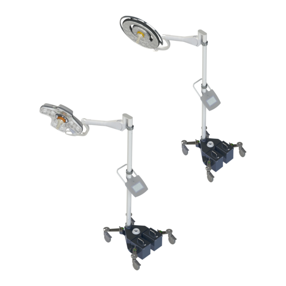
Page 12: Mechanical Representation
Technical characteristics Mechanical specifications 3.2.3 Mechanical representation Overall height of the lighting system 965 mm 2064 mm 777 mm Fig. 1: Overall height of the Maquet Rolite lighting system Maquet Rolite 12 / 48 NM 01833 EN 03... - Page 13 Technical characteristics Mechanical specifications Light rotation angles Fig. 2: Maquet Rolite rotation angles +15° / -15° +15° / -40° 360° 250° 330° Tab. 9: Maquet Rolite rotation angles Maquet Rolite 13 / 48 NM 01833 EN 03...
-
Page 14: Communication Protocol
Technical characteristics Communication protocol Communication protocol 3.3.1 General remarks regarding the CAN bus CAN bus (Control Area Network bus) is a serial communication medium that links real-time em- bedded systems with a high level of reliability. The following main properties are inherent to the structure of the CAN bus protocol: •... -
Page 15: Diagrams
Technical characteristics Diagrams Diagrams 3.4.1 Electrical wiring block diagram Fig. 3: Electrical wiring block diagram 3.4.2 Electrical connections Not applicable to this product. Maquet Rolite 15 / 48 NM 01833 EN 03... -
Page 16: Maintenance And Inspection Procedures
Maintenance and inspection procedures Tools required for maintenance Maintenance and inspection procedures AU TION Risk of equipment damage If adjustments are made incorrectly or not at all, the lighthead or installed equipment may drift. Make all adjustments (balance, stop and brakes) during installation and then after all maintenance operations. -
Page 17: Replacing The Batteries
AR NI NG Risk of burns If unsuitable batteries are used, they may explode due to the emission of gases or liquids. Always use batteries supplied by Getinge during installation and when repla- cing defective batteries. AR NI NG Risk of burns Improper storage of batteries after removal may trigger a fire. - Page 18 Maintenance and inspection procedures Periodic replacements • Slide the two new battery packs onto the slides until you hear a "click" to indicate that they are correctly in place. • Place the lighthead on the spring arm. Fig. 6: Locking the battery pins If the device is fitted with batteries and the batteries are charged: OTICE If the device is not connected to the mains for a period of at least 2 consecut-...
-
Page 19: Adjustments
Maintenance and inspection procedures Adjustments Adjustments 4.3.1 Installing the spring arms AR NI NG Risk of injury The metal half-rings can be sharp. The metal half-rings on the spring arm should be handled with care to avoid any risk of cuts. Adjusting the balance of the Ondaspace**/ Acrobat 2000 spring arm •... -
Page 20: Adjusting The Brakes
Maintenance and inspection procedures Adjustments Adjusting the tension in the OASYS spring arm • Removing the side covers • Insert the metal rod supplied with the spring arm into the side-hole nut • If the spring arm tends to move down, the spring arm tension is insufficient. -
Page 21: Lighthead Brakes
Maintenance and inspection procedures Adjustments PWD II 700 / VST 600 spring arm (5 tracks) • Use a flat-bladed screwdriver to remove the sliding ring mounting screw. • Slide the sliding ring along the arm. Fig. 10: Removing the mounting screw •... - Page 22 Maintenance and inspection procedures Adjustments On Maquet PowerLED II • Tighten to apply the brake. • Loosen to release the brake. Fig. 12: Adjusting the brakes OTICE Move the captive silicone cap out of the way to carry out this step. Make sure it is reinstalled correctly once the adjustment is made.
-
Page 23: Touchscreen Control Panel Settings
Maintenance and inspection procedures Adjustments • Check that the snap ring is correctly in place and adjust the brake if necessary: – Tighten to apply the brake. – Loosen to release the brake. • Slide the grey cover back into position in order to cover this part of the fork again. - Page 24 Maintenance and inspection procedures Adjustments Ø The brightness setting page is displayed. Setting the date and time and using the stopwatch/timer 1. Press Settings in the menu bar. Ø The Settings page is displayed (see above). 2. Press Date/Time Ø The page for date and time settings and stopwatch/timer functions is displayed. Adjusting the tilt handle 1.
-
Page 25: Screen Brightness
Maintenance and inspection procedures Adjustments 4.3.3.1 Screen brightness Fig. 16: Adjusting the screen brightness 1. Press Plus to increase the brightness of the touchscreen control panel or Minus to de- crease the brightness. Ø The screen brightness varies as shown by the brightness level indicator 2. -
Page 26: Date And Time
Maintenance and inspection procedures Adjustments 4.3.3.2 Date and time Fig. 17: Date and time settings Defining the date and time format 1. Press Date Format to choose the desired date display format. European, English or American date format can be set. Ø... -
Page 27: Information
Press Lightheads to display information about the lighthead(s) installed: product refer- ence, serial number, options available, usage hours. Press Maintenance to display the dates on which maintenance was performed and the Getinge contact details. Press Configuration to display the characteristics of the installed configuration (locations of tools and accessories). -
Page 28: Restarting The Touchscreen Control Panel
Maintenance and inspection procedures Adjustments 4.3.3.4 Restarting the touchscreen control panel Fig. 19: Reset page The Reset button has no effect on the Maquet PowerLED II. Restarting the touchscreen control panel 1. Press Restart Screen Ø A window is displayed. 2. Press the green tick to restart the touchscreen control panel. To cancel restarting and quit this window, press the red cross. -
Page 29: Maintenance
Maintenance Page • When button is pressed, the maintenance screen displays the following information: in- stallation date; name of the local Getinge contact; telephone number of the local contact. Fig. 21: Entering the password • Important: This information must be entered by a Getinge technician when the touchscreen control panel is installed. -
Page 30: Resetting And Restarting The Touchscreen Control Panel
Maintenance and inspection procedures Adjustments 4.3.3.6 Resetting and restarting the touchscreen control panel Fig. 22: Resetting and restarting the touchscreen control panel Reset (after ▪ Press this button to display the tools present and their change of tools) status after change. ▪... - Page 31 Maintenance and inspection procedures Adjustments • Turn off the lighthead(s). • Press the On/Off and Standard mode/ Ambient lighting mode buttons and hold them down for approximately 10 seconds, until one of the five LEDs on the bargraph is lit. – Each LED represents a different ad- dress.
-
Page 32: Conducting Backup Tests
5. If the test fails, press Maintenance information to access the maintenance information page, and then call the Getinge technical service department. Running a battery lifetime test (only with a Getinge backup) 1. Turn off the light. 2. Press Settings in the menu bar. -
Page 33: Mechanical Inspections
Maintenance and inspection procedures Mechanical inspections Mechanical inspections 4.4.1 Visual inspections • Check the stability of the light. • Check for any loose covers on the light. • Check the configuration for corrosion. • Check the configuration for any chipped or missing paint. -
Page 34: Checks
Maintenance and inspection procedures Mechanical inspections 4.4.2 Checks Check that the spring arms are balanced in all positions. Fig. 28: Checking the balance of the spring arms Check that the spring arms are balanced in all positions. Fig. 29: Checking the balance of the spring arms Check the vertical end-stop on the spring arm. - Page 35 Maintenance and inspection procedures Mechanical inspections Check that the brakes are properly adjusted on the spring arm for the single fork version. Fig. 32: Checking the adjustment of the brakes Check that the lighthead brakes are tightly fastened. Fig. 33: Checking the lighthead brakes Maquet Rolite 35 / 48 NM 01833 EN 03...
-
Page 36: Electrical Inspections
Maintenance and inspection procedures Electrical inspections Electrical inspections 4.5.1 Electrical checks • Check the mains lead connection to the Maquet Rolite base. • Check the installation and locking of the batteries. 4.5.2 Functional tests • Check that the LEDs operate correctly: 1. - Page 37 Maintenance and inspection procedures Electrical inspections Check that the touchscreen control panel and functions operate correctly. Ex: Adjusting the light field diameters, etc. Fig. 36: Checking the touchscreen control panel Switch over to battery mode and back to mains. Fig. 37: Checking the battery mode Check the battery charge indicator in the status bar of the touchscreen control panel.
-
Page 38: Hydraulic Inspections
Maintenance and inspection procedures Hydraulic inspections OTICE Protective goggles [Minimum UV Class 2 (EN 170) – Optical Class 1 – Orange shade] are recommended during installation and maintenance operations on surgical lights. Test the Laser mode (only on Maquet PowerLED II) 1. Press the Laser button and hold it until it flashes. -
Page 39: Electrical Safety Tests
Maintenance and inspection procedures Electrical safety tests Electrical safety tests Electrical safety measurements must be carried out using an IEC 62353-compat- ible electrical safety tester. Fig. 42: Electrical safety tests • Earth continuity should be measured between: 1. Point , protective earth (PE). 2. -
Page 40: Recording The Inspection
Recording the inspection Service protocol and tools used Recording the inspection Service protocol and tools used See also SW Service Protocol PM OR Lights Rolite PowerLED II-A-EN [} 41] Maquet Rolite 40 / 48 NM 01833 EN 03... - Page 41 Recording the inspection Service protocol and tools used 5.1.1 SW Service Protocol PM OR Lights Rolite PowerLED II-A-EN Maquet Rolite 41 / 48 NM 01833 EN 03...
- Page 42 Safety segment of the spring arm every 6 years Batteries every 3 years Please refer to the maintenance manual for more detailed instructions. Document name: SW Service Protocol PM OR Lights Maquet Rolite-C-FR www.getinge.com Maquet Rolite 42 / 48 NM 01833 EN 03...
- Page 43 Registration number (DD/MM/YYYY) Lubrication Non- Comp compl liant iant Lubrication of the lighthead bracket axles Lubrication of the slip rings Document name: SW Service Protocol PM OR Lights Maquet Rolite-C-FR www.getinge.com Maquet Rolite 43 / 48 NM 01833 EN 03...
- Page 44 Check that all visible screws are tightly fastened Electrical checks Non- Compliant Compliant Check the power cord connection Check the installation and locking of the batteries. Document name: SW Service Protocol PM OR Lights Maquet Rolite-C-FR www.getinge.com Maquet Rolite 44 / 48 NM 01833 EN 03...
- Page 45 Laser positioning assistance (PowerLed II only) Comfort Light mode (PowerLed II only) Change mode of the three TK colour temperatures and Volista NIR Boost (optional) Document name: SW Service Protocol PM OR Lights Maquet Rolite-C-FR www.getinge.com Maquet Rolite 45 / 48 NM 01833 EN 03...
- Page 46 Device no longer safe. Taking out of service is recommended. Comments 14 Processed by Name Date Signature YYYY 15 Facility (Required) Name / Title Date Signature YYYY Document name: SW Service Protocol PM OR Lights Maquet Rolite-C-FR www.getinge.com Maquet Rolite 46 / 48 NM 01833 EN 03...
- Page 47 Notes...
- Page 48 *MAQUET ROLITE, POWERLED II, VOLISTA, VOLISTA VISIONIR, AIM, COMFORT LIGHT, LASER POSITIONING, FSP, POWERLED, ROLITE, MAQUET, GETINGE and GETINGE GROUP are trademarks or registered trademarks of Getinge AB, its divisions or its subsidiaries. **ACROBAT and ONDASPACE are trademarks or registered trademarks of Ondal Holding GmbH, its divisions or its subsidiaries.
Need help?
Do you have a question about the Maquet PowerLED II 700 and is the answer not in the manual?
Questions and answers