
Subscribe to Our Youtube Channel
Related Manuals for Cooper & Hunter VITAL INVERTER Series


Summary of Contents for Cooper & Hunter VITAL INVERTER Series
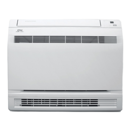
- Page 1 ПОБУТОВИЙ КОНДИЦІОНЕР СЕРІЯ CONSOLE INVERTER CH-S09FVX-NG CH-S12FVX-NG CH-S18FVX-NG Cooper & Hunter International Corporation, www.cooperandhunter.com...
-
Page 3: Пояснення Символів
КЕРІВНИЦТВО З ЕКСПЛУАТАЦІЇ УКР ПОЯСНЕННЯ СИМВОЛІВ Цей символ вказує на ризик смерті або серйозної травми. ОБЕРЕЖНО Цей символ вказує на ризик травми або матеріального збитку. УВАГА Позначає важливу, але не пов’язану з будь-якою небезпекою, ПРИМІТКА інформацію, яка використовується для попередження про ризик... - Page 4 ХОЛОДОАГЕНТ займистим холодоагентом».) Пристрій запо- Пристрій Перед монта- внений займистим газом R32. Під час ремон- заповнений жом пристрою ту чітко дотримуйтесь інструкцій виробника. пожежоне- варто вивчити Майте на увазі, що холодоагенти можуть не безпечним інструкцію газом R32. користувача. мати запаху. Уважно прочитайте інструкцію Перед...
- Page 5 КЕРІВНИЦТВО З ЕКСПЛУАТАЦІЇ УКР БЕЗПЕЧНА ЕКСПЛУАТАЦІЯ ЛЕГКОЗАЙМИСТОГО ХОЛОДАГЕНТА Вимоги до кваліфікації Примітки з технічного спеціаліста з встановлення та обслуговування обслуговування ▷ Переконайтеся, що зона обслуговуван- ня або площа кімнати відповідає вимогам ▷ Всі робітники, залучені до роботи з холо- паспортної таблички. дильною...
-
Page 6: Запобіжні Заходи
Заправка пристрою ЗАПОБІЖНІ ЗАХОДИ холодоагентом ▷ Використовуйте спеціалізовані пристрої ▷ Нестабільне електроживлення або не- для заправки, які призначені для R32. Пе- правильно влаштована проводка можуть реконайтесь, що холодоагенти разних ти- призвести до ураження електричним пів не змішуються. струмом, займання або несправності ▷... - Page 7 КЕРІВНИЦТВО З ЕКСПЛУАТАЦІЇ УКР ЗАПОБІЖНІ ЗАХОДИ ▷ Жовто-зелений дріт – це дріт для зазем- ▷ Не мийте кондиціонер водою. В іншому лення, який неможна використовувати для випадку можливе ураження електрич- інших цілей. ним струмом. ▷ Кондиціонер є електропристроєм першого ▷ Не розпилюйте воду на внутрішній блок класу.
- Page 8 ВСТАНОВЛЕННЯ ВНУТРІШНЬОГО БЛОКУ Інструменти, необхідні для монтажу 1. Вимірювач рівня 2. Викрутка 3. Перфоратор 4. Свердлильна голівка 5. Вальцовка 6. Гайковий ключ 7. Розвідний ключ 8. Труборіз 9. Детектор протікання 10. Вакуумний насос 11. Манометрична станція 12. Мультиметр 13. Внутрішній шестигранний ключ 14.
- Page 9 КЕРІВНИЦТВО З ЕКСПЛУАТАЦІЇ УКР ВСТАНОВЛЕННЯ ВНУТРІШНЬОГО БЛОКУ Вибір місця монтажу 8. Пристрій повинен знаходиться на відстані не менше 1 метра від будь-якого теле- або радіо приймача. ▷ Таке місце, де холодне повітря може 9. Змонтований пристрій може створювати поширюватися по кімнаті. перешкоди...
- Page 10 ВСТАНОВЛЕННЯ ВНУТРІШНЬОГО БЛОКУ Трубопровод холодоагенту УВАГА 1. Просвердліть отвір (діаметром 55 мм) у Мінімальна допустима довжина місці, позначеному символом на ма- ▷ Рекомендована найкоротша довжина люнку нижче. траси становить 2,5 м, щоб уникнути 2. Розташування отвору залежить від того, з шуму...
- Page 11 КЕРІВНИЦТВО З ЕКСПЛУАТАЦІЇ УКР ВСТАНОВЛЕННЯ ВНУТРІШНЬОГО БЛОКУ Свердління отвору в стіні, та 5. Ізолюйте внутрішню дренажну трубу ізо- ляційним матеріалом товщиною 10 мм або прокладання в ньому труби більше, щоб запобігти утворенню конден- Для стін із залізобетону обов’язково вико- сату. ристовуйте...
- Page 12 МОНТАЖ ВНУТРІШНЬОГО БЛОКУ Підготовка ▷ Відкрийте передню панель, видаліть 4 гвинти та зніміть передню решітку, потяг- нувши її вперед. ▷ Дотримуйтеся стрілок, щоб від’єднати за- стібки на передній частині корпусу та зняти панель. ▷ При розбиранні приладу, дотримуйтеся на- веденої нижче процедури. Для...
- Page 13 КЕРІВНИЦТВО З ЕКСПЛУАТАЦІЇ УКР МОНТАЖ ВНУТРІШНЬОГО БЛОКУ Монтажну пластину слід встановити на стіні, 3. Після завершення підключення труби хо- яка може витримати вагу внутрішнього бло- лодоагенту та дренажної труби запіньте ку. нещільності монтажного отвору. Зазор 1. Тимчасово закріпіть монтажну пластину може...
- Page 14 МОНТАЖ ВНУТРІШНЬОГО БЛОКУ Підключення труби внутрішнього блоку Вибір мідних і теплоізолюючих матеріалів 1. Направте з’єднання труби на відповідний Використовуючи промислові мідні труби та фі- розтруб. тинги, дотримуйтеся наступного: 2. Попередньо затягніть вручну накидну гай- 1. Ізоляційний матеріал: пінополіетилен ку. 2. Коефіцієнт теплопровідності: від 0,041 до 0,052 Вт/мК...
- Page 15 КЕРІВНИЦТВО З ЕКСПЛУАТАЦІЇ УКР МОНТАЖ ВНУТРІШНЬОГО БЛОКУ Перевірка на витіки газу УВАГА 1. Перевірте наявність витоку газу після вида- 1. Надійно ізолюйте з’єднання труб. Непов- лення повітря. на ізоляція може призвести до появи кон- 2. Див. розділи про видалення повітря та пе- денсату.
- Page 16 МОНТАЖ ВНУТРІШНЬОГО БЛОКУ 4. Потягніть дроти, щоб переконатися, що УВАГА вони надійно зафіксовані, а потім закрипіть дроти за допомогою фіксатора. 1. Не використовуйте скручені дроти, бага- тожильні дроти, подовжувачі або зірко- подібні з’єднання, оскільки вони можуть спричинити перегрів, ураження елек- тричним...
- Page 17 КЕРІВНИЦТВО З ЕКСПЛУАТАЦІЇ УКР РЕГЛАМЕНТНА ПЕРЕВІРКА ПІСЛЯ МОНТАЖУ Перевірка після монтажу Пункти перевірки Можливі несправності Ситуація Чи прилад найдіно закріплений? Пристрій може впасти, тремтіти або шуміти Чи була виконана перевірка на витік Це може спричинити недостатню холодоагенту? холодопродуктивність Чи достатня теплоізоляція? Це...
- Page 18 ТЕХНІЧНЕ ОБСЛУГОВУВАННЯ ▷ У разі миття передньої панелі водою, ви- ПРИМІТКА тріть її тканиною, а потім висушіть у тіні. ▷ Перед перевіркою та обслуговуванням 4. Прикріпіть передню панель. пристрою. БУДЬ ЛАСКА, встановіть пере- ▷ Вставте передню панель у пази блоку (3 микач...
- Page 19 КЕРІВНИЦТВО З ЕКСПЛУАТАЦІЇ УКР 2. Фільтри 6. Промийте повітряні фільтри водою або по- чистіть їх пилососом. ▷ Якщо пил не видаляється легко, про- 1. Протріть їх сухою м’якою тканиною. мийте їх нейтральним миючим засобом, 2. Зніміть фільтр повітря. розведеним теплою водою, а потім ▷...
- Page 20 ЧАСТИНИ ПРИСТРОЮ ТА ЇХ ФУНКЦІЇ УВАГА ▷ Перш ніж відкривати передню панель, обов’язково зупиніть роботу приладу та вимкніть вимикач. Не торкайтеся металевих частин усередині внутрішнього блоку, оскільки це може призвести до травм. 1. Титано-апатитовий фотока- талітичний фільтр 2. Вихід повітря 3.
- Page 21 КЕРІВНИЦТВО З ЕКСПЛУАТАЦІЇ УКР ПУЛЬТ ДИСТАНЦІЙНОГО КЕРУВАННЯ ТА ЙОГО ЕКСПЛУАТАЦІЯ Кнопки на пультi Графічні значки на дистанційного керування екрані ПДК Налаштування швидкості вентилятора Передача сигналу Функція X-FAN Налаштування температури Темп. Температура в приміщенні тип дисплея Температура зовні. Автоматичний режим Режим охолодження Режим...
- Page 22 ПУЛЬТ ДИСТАНЦІЙНОГО КЕРУВАННЯ ТА ЙОГО ЕКСПЛУАТАЦІЯ Кнопка ПРИМІТКА ▷ Це пульт дистанційного керування загаль- Натисніть цю кнопку, щоб обрати потрібний ного призначення. Його можна використо- режим роботи. вувати, також, для багатофункціональних кондиціонерів. Якщо на пульті натиснути кнопку, яка відповідатиме функції, якої ця модель...
- Page 23 КЕРІВНИЦТВО З ЕКСПЛУАТАЦІЇ УКР Кнопка Кнопка Ця кнопка використовується для налашту- Натисніть цю кнопку, щоб обрати кут коли- вання швидкості обертання вентилятора в вання вгору-вниз. Кут обдування вентилято- послідовності від AUTO, ра можна вибрати за схемою, яка наведена та назад до AUTO. нижче: низька...
- Page 24 Кнопка час на дисплеї пульта буде відображатися «1 година», а в показник температури «88» Натисніть цю кнопку, щоб увімкнути або буде відображати температуру останньої вимкнути функції оздоровлення та очищення. заданої кривої режиму сну та блимати (при Натисніть цю кнопку в перший раз, щоб запу- першому...
- Page 25 КЕРІВНИЦТВО З ЕКСПЛУАТАЦІЇ УКР Кнопка Натисніть кнопку T-ON/T-OFF, щоб запу- стити таймер автоматичного вимкнення. Щоб скасувати програму автоматичного таймера, Натисніть цю кнопку: безшумна робота кон- диціонера можлива в Автоматичному тихому просто натисніть кнопку ще раз. Налашту- режимі (Auto Quiet) (відображається значок вання...
-
Page 26: Функція Енергозбереження
Заміна батарейок в пульту ОПИС ФУНКЦІЙ дистанційного керування КОМБІНАЦІЙ КНОПОК Функція енергозбереження Щоб увімкнути або вимкнути функцію енергозбереження, в режимі охолоджен- ня одночасно натисніть кнопки «TEMP» та «CLOCK». Коли функція енергозбереження запущена, на пульті дистанційного керуван- 1. Натисніть на задню частину пульта дистан- ційного... - Page 27 КЕРІВНИЦТВО З ЕКСПЛУАТАЦІЇ УКР КОНСТРУКЦІЯ ЗОВНІШНЬОГО БЛОКУ ПРИМІТКА ▷ Фактичний продукт може відрізнятися від ілюстрованого.
- Page 28 РЕКОМЕНДАЦІЇ З МОНТАЖУ ЗОВНІШНЬОГО БЛОКУ УВАГА переконайтеся, що пристрій працює в режимі охолодження. Потім повністю закрийте клапан на стороні високого тиску (клапан рідини). Приблизно через 30–40 секунд повністю закрийте кла- пан на стороні низького тиску (газовий кран), негайно зупиніть установку та відключіть...
- Page 29 КЕРІВНИЦТВО З ЕКСПЛУАТАЦІЇ УКР РЕКОМЕНДАЦІЇ З МОНТАЖУ ЗОВНІШНЬОГО БЛОКУ ВИБІР МІСЦЯ ДЛЯ УВАГА МОНТАЖУ вильний електричний провід. Основні вимоги Погане підключення може призвести до Встановлення пристрою в таких місцях ураження електричним струмом або по- може призвести до несправності. Якщо жежі. цього...
-
Page 30: Заходи Безпеки
РЕКОМЕНДАЦІЇ З МОНТАЖУ ЗОВНІШНЬОГО БЛОКУ Заходи безпеки Вимоги до заземлення Необхідно дотримуватися правил елек- Кондиціонер відноситься до першого тробезпеки під час встановлення агре- класу електричних приладів. Він пови- гату. нен бути належним чином заземлений Відповідно до локальних стандартів роботи мають бути виконані профе- електробезпеки... - Page 31 КЕРІВНИЦТВО З ЕКСПЛУАТАЦІЇ УКР МОНТАЖ ЗОВНІШНЬОГО БЛОКУ Крок 1: Крок 2: Зафіксуйте опору зовнішнього Встановіть дренажне з’єднання блоку (лише для деяких моделей) 1. Під’єднайте з’єднання зовнішнього дрена- (виберіть її відповідно до фактичної ситуа- жу до отвору на шасі, як показано на ма- ції...
- Page 32 МОНТАЖ ЗОВНІШНЬОГО БЛОКУ Крок 4: Крок 5: З’єднайте труби внутрішнього та Підключеня зовнішнього зовнішного блоків електричного провіду 1. Викрутіть гвинт на правій ручці зовнішньо- 1. Зніміть затискач дроту; підключіть провід го блоку, а потім зніміть ручку. живлення та провід керування сигналом (тільки...
- Page 33 КЕРІВНИЦТВО З ЕКСПЛУАТАЦІЇ УКР МОНТАЖ ЗОВНІШНЬОГО БЛОКУ Крок 6: Встановлення дренажного шлангу 1. Труби слід розташувати уздовж стіни, зі- гнути коректно і можливо сховано у ко- робі/стіні. Мінімальний півдіаметр вигину труби становить 10 см. 2. Якщо зовнішній блок вище за отвір у стіні, ви...
- Page 34 ВИПРОБУВАННЯ ТА ЕКСПЛУАТАЦІЯ Скористайтеся вакуумним Перевірка після монтажу насосом ▷ Після закінчення монтажу виконайте на- 1. Відкрутіть ковпачки вентилів рідини та ступні дії: газу та гайку вентиля для заправки холо- Елементи, для Можлива несправність доагента. перевірки 2. Підключіть шланг заправки манометричної Чи...
- Page 35 КЕРІВНИЦТВО З ЕКСПЛУАТАЦІЇ УКР КОНФІГУРАЦІЯ З’ЄДНУВАЛЬНОЇ ТРУБКИ Додаткова кількість 1. Стандартна довжина магістральної труб- ки: 5 м, 7,5 м, 8 м. холодоагента R32 2. Мінімальна довжина магістральної трубки. Для агрегату зі стандартною магістраль- ною трубкою, довжиною 5м, обмежень по мінімальній довжині магістральної трубки немає.
- Page 36 МЕТОД ПОДОВЖЕННЯ ТРУБОК Е: Вальцювання ПРИМІТКА ▷ Зробіть вальцювання за допомогою розши- Неправильне подовження трубки – основна рювача. причина витоку холодоагенту. Подовжуйте трубки виключно відповідно до наступних інструкцій: A: Відріжте трубку ▷ Визначте потрібну довжину труби відповід- а но до відстані між внутрішнім та зовнішнім а...
- Page 37 КЕРІВНИЦТВО З ЕКСПЛУАТАЦІЇ УКР ІНСТРУКЦІЯ ДЛЯ СПЕЦІАЛІСТА Пристрої, що використовують горючі хо- ▷ чи постійне заземлення. лодоагенти, слід перевіряти згідно з такими Перевірка наявності холодоагента. пунктами: До, та під час виконання робіт, робочу об- ▷ чи відповідає обсяг заправленого холодо- ласть...
- Page 38 тів всі джерела електроживлення повинні Кабелі. бути відключені до того, як будуть зняті Переконайтеся, що кабелі не зношені, не герметичні кришки і т.д. пошкоджені, що не піддаються надмірному ▷ Якщо електроживлення обладнання під тиску, вібрації, не торкаються гострих країв час обслуговування абсолютно необхідне, інших...
- Page 39 КЕРІВНИЦТВО З ЕКСПЛУАТАЦІЇ УКР E. Якщо відкачати холодоагент неможливо, охолоджені. спорудіть колектор таким чином, щоб хо- Устаткування для збору повинно бути в ро- лодоагент можна було вилучити з різних бочому стані, мати повний набір інструкцій, частин системи. та має підходити для збору всіх холодоаген- F.
- Page 40 EWPE SMART WI-FI CONTROL Додаток Wi-Fi і Операційні системи налаштування Вимоги до смартфону користувача: Підтримка iOS7.0 і вище Підтримка Android 4.4 і вище Завантаження та 4. Натисніть + у правому верхньому куті го- ловної сторінки, щоб вибрати додати ваш встановлення пристрій.
- Page 41 КЕРІВНИЦТВО З ЕКСПЛУАТАЦІЇ УКР Розширені налаштування Натисніть FUNC у нижньому лівому куті в інтерфейсі роботи пристрою, щоб увійти до додаткових налаштувань Налаштування Swing Щоб увімкнути або вимкнути функцію гой- дання, клацніть «Гойдання вгору вниз» або «Гойдання вліво вправо». Клацніть стрілку в нижньому...
-
Page 42: Технічні Характеристики
ТЕХНІЧНІ ХАРАКТЕРИСТИКИ Модель CH-S09FVX-NG CH-S12FVX-NG CH-S18FVX-NG холод кВт 3.52 Продуктивність тепло кВт 5.33 Джерело електроживлення ~ 220-240В/50Гц/1Ф холод кВт 0.72 1.55 Номінальна потужність тепло кВт 0.73 0.96 500/430/410/370/ 600/520/480/440/ 700/650/580/520/ Повітропродуктивність м³/г 330/280/250 400/360/280 460/410/320 вн. блок дБ(А) 39/36/33/31/29/26/23 44/40/38/36/33/29/25 47/45/42/40/37/35/31 (м/с/мак) Рівень... - Page 44 *Cooper&Hunter постійно працює над удоско- наленням своєї продукції, тому інформація, яка приведена в цьому керівництві, може бути зміне- на без попереднього повідомлення споживачів. 2023/1...
- Page 45 OWNER’S MANUAL Split Air Conditioner VITAL INVERTER Series CH-S09FTXLA2-NG CH-S12FTXLA2-NG CH-S18FTXLA2-NG CH-S24FTXLA2-NG For proper operation, please read and keep this manual carefully. Designed by Cooper&Hunter International Corporation, FL Miami, USA www.cooperandhunter.com...
-
Page 47: Explanation Of Symbols
OWNER’S MANUAL EXPLANATION OF SYMBOLS This symbol indicates the possibility of death or WARNING serious injury. This symbol indicates the possibility of injury or CAUTION damage to property. Indicates important hazard-related NOTICE information, used to indicate risk of property damage. EXCEPTION CLAUSES Manufacturer will bear no responsibilities when personal injury or property loss is caused by the following reasons:... - Page 48 REFRIGERANT Before install Appliance the appliance, filled with read the flammable installation gas R32. manual first. This appliance is not intended for use by Before use the Before repair persons (including children) with reduced appliance, the appliance, read the physical, sensory or mental capabilities, or lack read the service owner’s of experience an d knowledge, unless they have...
-
Page 49: Safety Operation Of Flammable Refrigerant
OWNER’S MANUAL SAFETY OPERATION OF FLAMMABLE REFRIGERANT Qualification requirement for Maintenance notes installation and maintenance man ▷ Check whether the maintenance area or the room area meet the requirement of the ▷ All the work men who are engaging in the nameplate. -
Page 50: Safety Instructions For Transportation And Storage
Filling the refrigerant ▷ Air Conditioner should properly ▷ Use the refrigerant filling appliances specia- grounded. Incorrect grounding may cause lized for R32. Make sure that different kinds electric shock. of refrigerant won’t contaminate with each ▷ Do not put through the power before other. -
Page 51: Operation And Maintenance
OWNER’S MANUAL SAFETY PRECAUTIONS ▷ Do not step on top panel of outdoor unit, or WARNING put heavy objects. It may cause damage or personal injury. When below phenomenon Operation occurs, please turn off air conditioner and and Maintenance disconnect power immediately, and then contact the dealer or qualified professionals ▷... -
Page 52: Installation Notice
INSTALLATION NOTICE WARNING pressure side (liquid valve). About 30-40 Space to the wall At least 15cm seconds later, fully close the valve at low Space to the wall pressure side (gas valve), immediately stop At least 15cm the unit and disconnect power. Please note that the time for refrigerant recovery should not exceed 1 minute. -
Page 53: Selection Of Installation Location
OWNER’S MANUAL INSTALLATION NOTICE SELECTION OF INSTALLATION LOCATION Tools for installation Basic requirement Installing the unit in the following places 1. Level meter 2. Screw driver may cause malfunction. If it is unavoidable, 3. Impact drill please consult the local dealer: 4. -
Page 54: Safety Precaution
SELECTION OF INSTALLATION LOCATION Safety precaution Grounding requirement Must follow the electric safety regulations 1. The air conditioner is the first class electric when installing the unit. appliance. It must be properly grounded According to the local safety regulations, with specialized grounding device by a use qualified power supply circuit and air professional. - Page 55 OWNER’S MANUAL MAINTENANCE 4. Attach the front panel. NOTICE ▷ Insert the front panel into the grooves of the unit (3 places). ▷ Before inspection and maintenance of the ▷ Attach the string to the right, inner-side of unit. PLEASE set power switch to “OFF” to the front grille.
-
Page 56: Maintenance
MAINTENANCE 2 Filters: 6. Wash the air filters with water or clean them with vacuum cleaner. ▷ If the dust does not come off easily, wash 1. Wipe them with dry soft cloth them with neutral detergent thinned with 2. Remove the air filter. lukewarm water, then dry them up in the ▷... -
Page 57: Installation Of Indoor Unit
OWNER’S MANUAL INSTALLATION OF INDOOR UNIT Selection of installation location. 8. The unit is at least 1 metre away from any television or radio 9. Set (unit may cause interference with the ▷ Such a place where cool air can be picture or sound). -
Page 58: Refrigerant Piping
INSTALLATION OF INDOOR UNIT Refrigerant piping CAUTION 1. Drill a hole ( 55mm in diameter ) in the spot Min.allowable length indicated by the symbol in the illustration as below . ▷ The suggested shortest pipe length is 2.5m, 2. The location of the hole is different in order to avoid noise from the outdoor depending on which side of the pipe is taken unit and vibration. -
Page 59: Boring A Wall Hole And Installing Wall Embedded Pipe
OWNER’S MANUAL INSTALLATION OF INDOOR UNIT Boring a wall hole and installing 5. Insulate the indoor drain pipe with 10mm or more of insulation material to prevent wall embedded pipe condensation. 6. Remove the air filters and pour some water For walls containing metal frame or metal board, into the drain pan to check the water flows be sure to use a wall embedded pipe and wall... - Page 60 INSTALLATION OF INDOOR UNIT Preparation 2)Upper casing ▷ Open the front panel, remove the 4 screws and dismount the front grille while pulling it forward. ▷ Follow the arrows to disengage the clasps on the front case to remove it. ▷...
- Page 61 OWNER’S MANUAL INSTALLATION OF INDOOR UNIT The mounting plate should be installed on a 3. Once refrigerant piping and drain piping wall which can support the weight of the indoor connections are complete, fill in the gap of unit. the through hole with putty. A gap can lead 1.
- Page 62 INSTALLATION OF INDOOR UNIT Connect the pipe of indoor unit Selection of copper and heat insulation materials 1. Aim the pipe joint at the corresponding bellmouth. When using commercial copper pipes and 2. Pretighten the union nut with hand. fittings, observe the following: 1.
- Page 63 OWNER’S MANUAL INSTALLATION OF INDOOR UNIT Checking for gas leakage CAUTION 1. Check for leakage of gas after air purging 1. Insulate the joint of the pipes securely. 2. See the sections on air purges and gas leak Incomplete insulation may lead to water checks in the installation manual for the leakage.
- Page 64 INSTALLATION OF INDOOR UNIT 4. Pull wires to make sure that they are securely CAUTION latches up, then retain wires with wire retainer. 1. Do not use tapped wires, stranded wires, extensioncords, or starburst connections, Sensor securing plate as they may cause overheating, electrical shock, or fire.
-
Page 65: Routine Check After Installation
OWNER’S MANUAL ROUTINE CHECK AFTER INSTALLATION Check after installation Items to be checked Possible malfunction Situation Has it been fixed firmly? The unit may drop,shake or emit noise. Have you done the refrigerant It may cause insufficient refrigerating leakage test? capacity. -
Page 66: Part Names And Their Functions
PART NAMES AND THEIR FUNCTIONS WARNING ▷ Before opening the front panel, be sure to stop the operation and turn the breaker OFF. Do not touch the metal parts on the inside of the indoor unit, as it may result in injury. 1. -
Page 67: Introduction For Icons On Display Screen
OWNER’S MANUAL OPERATION AND INTRODUCTION OF REMOTE CONTROLLER BUTTONS ON REMOTE INTRODUCTION FOR CONTROLLER ICONS ON DISPLAY SCREEN Set fan speed Send signal X-FAN button Set temp. Temp. Indoor ambient temp. display type Outdoor ambient temp. Auto mode Cool mode Dry mode Fan mode Heat mode... -
Page 68: Introduction For Buttons On Remote Controller
INTRODUCTION FOR BUTTONS ON REMOTE CONTROLLER Button NOTICE This button is used for setting Fan Speed in ▷ This is a general use remote controller, the sequence that goes from AUTO, it could be used for the air conditioners , then back to Auto. with multifunction;... - Page 69 OWNER’S MANUAL ▷ This remote controller is universal . If any ▷ Sleep 3 – the sleep curve setting under Sleep command , ais sent out, the unit will mode by DIY; carry out the command as 1. Under Sleep 3 mode, press “Turbo” button ▷...
- Page 70 Button After press of this button, disappears and «ON «blinks. 00:00 is displayed for ON time Press this button, could select displaying the setting. Within 5 seconds, press «+» or «-» indoor setting temperature or indoor ambient button on to adjust the time value.Every press temperature.When the indoor unit firstly power of either button changes the time setting by on it will display the setting temperature, if the...
-
Page 71: Function Introduction For Combination Buttons
OWNER’S MANUAL FUNCTION INTRODUCTION FOR COMBINATION BUTTONS Child lock function Press «-» and «+» buttons simultaneously to turn on or turn off child lock function. When child lock function is on, « » icon is displayed on remote controller.If you operate the remote controller, the «... -
Page 72: Replacement Of Batteries In Remote Controller
Replacement of batteries in remote controller 1. Press the back side of remote controller marked with « », as shown in the fig, and then push out the cover of battery box along the arrow direction. 2. Replace two 7# (AAA 1.5V) dry batteries, and make sure the position of «+»... - Page 73 OWNER’S MANUAL CONSTRUCTION OF THE OUTDOOR UNIT air inlet air outlet NOTICE ▷ Actual product may be different from above graphics, please refer to actual product.
-
Page 74: Installation Notice
INSTALLATION NOTICE CAUTION mode. Then, fully close the valve at high pressure side (liquid valve). About 30–40 seconds later, fully close the valve at low pressure side (gas valve), immediately Space to the obstruction stop the unit and disconnect power. At least 50cm Please note that the time for refrigerant recovery should not exceed 1 minute. -
Page 75: Selection Of Installation Location
OWNER’S MANUAL INSTALLATION NOTICE Tools for installation SELECTION OF INSTALLATION LOCATION 1. Level meter 2. Screw driver Basic requirement 3. Impact drill Installing the unit in the following places 4. Drill head may cause malfunction. If it is unavoidable, 5. Open-end wrench please consuit the local dealer: 6. - Page 76 INSTALLATION NOTICE Safety precaution Grounding requirement Must follow the electric safety regulations The air conditioner is the first class when installing the unit. electric appliance.It must be properly According to the local safety regulations, grounding with specialized grounding use qualified power supply circuit and air device by a professional.
-
Page 77: Installation Of Outdoor Unit
OWNER’S MANUAL INSTALLATION OF OUTDOOR UNIT Step 1: Step 2: Fix the support of outdoor unit Install drain joint (select it according to the actual installation (only for some models) situation) 1. Connect the outdoor drain joint into the hole on the chassis, as shown in the picture 1. - Page 78 INSTALLATION OF OUTDOOR UNIT Step 4: Step 5: Connect indoor and outdoor pipes Connect outdoor electric wire 1. Remove the screw on the right handle of 1. Remove the wire clip; connect the power outdoor unit and then remove the handle. connection wire and signal control wire (only for cooling and heating unit) to the wiring terminal according to the color;...
- Page 79 OWNER’S MANUAL INSTALLATION OF OUTDOOR UNIT Step 6: Neaten the pipes 1. The pipes should be placed along the wall, bent reasonably and hidden possibly. Min. semidiameter of bending the pipe is 10cm. 2. If the outdoor unit is higher than the wall hole, you must set a U-shaped curve in the pipe before pipe goes into the room, in order to prevent rain from getting into the room.
-
Page 80: Test And Operation
TEST AND OPERATION Use vacuum pump Check after installation ▷ Check according to the following requirement 1. Remove the valve caps on the liquid valve after finishing installation. and gas valve and the nut of refrigerant Items to be checked Possible malfunction charging vent. -
Page 81: Configuration Of Connection Pipe
OWNER’S MANUAL CONFIGURATION OF CONNECTION PIPE Additional refrigerant 1. Standard length of connection pipe: 5 m, 7.5 m, 8 m. charging amount for R32 2. Min. length of connection pipe. For the unit with standard connection pipe of 5 m, there is no limitation for the min length of connection pipe. -
Page 82: Pipe Expanding Method
PIPE EXPANDING METHOD E: Expand the port NOTICE ▷ Expand the port with expander. Improper pipe expanding is the main cause of refrigerant leakage. Please expand the pipe according to the following steps: A: Cut the pipe ▷ Confirm the pipe length according to the distance of indoor unit and outdoor unit. - Page 83 OWNER’S MANUAL SPECIALIST’S MANUAL The following checks shall be applied to i.e. non-sparking, adequately sealed installations using flammable refrigerants: intrinsically safe. ▷ the charge size is in accordance with the Presence of fire extinguisher room size within which the refrigerant If any hot work is to be conducted on the containing parts are installed;...
- Page 84 affected. This shall include damage to cables, containing chlorine shall be avoided as the excessive number of connections, terminals chlorine may react with the refrigerant and not made to original specification, damage to corrode the copper pipe-work. seals, incorrect fitting of glands, etc. ●...
- Page 85 OWNER’S MANUAL Labelling flammable refrigerant does not remain within Equipment shall be labelled stating that the lubricant. The evacuation process shall be it has been de-commissioned and emptied carried out prior to returning the compressor of refrigerant. The label shall be dated and to the suppliers.
-
Page 86: Operating Systems
EWPE SMART WI-FI CONTROL APPLICATION Wi-Fi app and set up Operating systems Requirement for user’s smart phone: iOS system Support iOS7.0 and above version Android system Support Android 4.4 and above version Download and installation Scan the QR code or search Ewpe Smart in the application reset tools according to actual situation. -
Page 87: Swing Settings
OWNER’S MANUAL Swing Settings Click Up down swing or Left right swing to turn on or turn off swing function. Click the arrow at the right lower corner of icon to enter the set swing range. Preset Setting Select Timer to set preset times of your choice Other function settings Homepage menu... -
Page 88: Specification
SPECIFICATION Model CH-S09FVX-NG CH-S12FVX-NG CH-S18FVX-NG cooling 3.52 Capacity heating 5.33 Power supply ~ 220-240V/50Hz/1Ph cooling 0.72 1.55 Rated capacity heating 0.73 0.96 500/430/410/370/ 600/520/480/440/ 700/650/580/520/ Air flow rate m3/h 330/280/250 400/360/280 460/410/320 IDU (min/ mid/ db(А) 39/36/33/31/29/26/23 44/40/38/36/33/29/25 47/45/42/40/37/35/31 max) Soud level rate db(А) Refrigerant type... - Page 90 *Cooper&Hunter is constantly working on improvement by pouring their products, so what information given in this manual, may be changed- without prior notice to consumers. 2023/1...
Need help?
Do you have a question about the VITAL INVERTER Series and is the answer not in the manual?
Questions and answers