Table of Contents
Advertisement
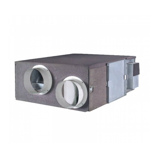
Energy Recovery Ventilation
System
Owner's Manual
Commercial Air Conditioners
Applicable Models (V Series):
CH-HRV3.5K
CH-HRV5K
CH-HRV8K
CH-HRV10K
CH-HRV15M
CH-HRV20M
Thank you for choosing commercial air conditioners.
Please read this Owner's Manual carefully before operation and retain it for
future reference.
If you have lost the Owner's Manual, please contact the local agent or visit www.
cooperandhunter.com.
Advertisement
Table of Contents


Need help?
Do you have a question about the V Series and is the answer not in the manual?
Questions and answers