Table of Contents
Advertisement
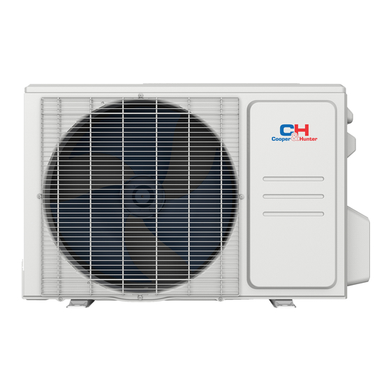
SOPHIA
MULTI-ZONE
INVERTER
SPLIT AIR CONDITIONER
WITH HEAT PUMP
INSTALLATION MANUAL
OUTDOOR UNIT
Models:
CH-18MSPH-230VO
CH-28MSPH-230VO
CH-36MSPH-230VO
CH-48MSPH-230VO
IMPORTANT NOTE:
Read this manual carefully before
•
installing or operating your new air
conditioning unit. Make sure to save
this manual for future reference.
This manual only describes the installation of
•
the outdoor unit. When installing the indoor unit,
refer to the installation manual of the indoor unit.
Advertisement
Table of Contents

Related Manuals for Cooper & Hunter SOPHIA CH-18MSPH-230VO


Summary of Contents for Cooper & Hunter SOPHIA CH-18MSPH-230VO
-
Page 1: Installation Manual
SOPHIA MULTI-ZONE INVERTER SPLIT AIR CONDITIONER WITH HEAT PUMP INSTALLATION MANUAL OUTDOOR UNIT Models: CH-18MSPH-230VO CH-28MSPH-230VO CH-36MSPH-230VO CH-48MSPH-230VO IMPORTANT NOTE: Read this manual carefully before • installing or operating your new air conditioning unit. Make sure to save this manual for future reference. This manual only describes the installation of •... -
Page 2: Table Of Contents
Table of Contents Installation Manual Accessories ..............04 Safety Precautions ..........05 Installation Overview .......... 06 Installation Diagram ..........07 Speci cations .............. 08 Indoor Unit Installation ......Outdoor Unit Installation ......... 09 A. Outdoor Unit Installation Instructions ..09 B. - Page 3 Refrigerant Piping Connection ....12 Wiring ..............14 A. Outdoor Unit Wiring ......14 B. Wiring Figure .......... 16 Air Evacuation ............20 A. Evacuation Instructions ......... 20 B. Note on Adding Refrigerant ...... Test Run ........................Function of Automatic Wiring/Piping Correction ..
-
Page 4: Accessories
Accessories The air conditioning system comes with the following accessories. Use all of the installation parts and accessories to install the air conditioner. Improper installation may result in water leakage, electrical shock, or fire, or cause the equipment to fail. Name Shape Quantity... -
Page 5: Safety Precautions
Safety Precautions Read safety precautions before installation Incorrect installation due to ignoring instructions can cause serious damage or injury. The seriousness of potential damage or injuries is classified as either a WARNING or CAUTION. Failure to observe a warning may result in death. The appliance must be installed in accordance with national regulations. -
Page 6: Installation Overview
Installation Overview INSTALLATION ORDER Install the outdoor unit Connect the wires Connect the refrigerant pipes (Page 9) (Page 14) (Page 12) Perform a test run Evacuate the refrigeration (Page 22) system (Page 20) Page 6 ... -
Page 7: Installation Diagram
Installation Diagram Installation Diagram Fig. 4.1 Safety Precautions CAUTION CAUTION To prevent unnecessary damage to the wall, This illustration is for explanation purposes • • use a stud nder to locate studs. only. The actual shape of your air A minimum pipe run of 9.8 ft (3 m) is required condtioner may be slightly di erent. -
Page 8: Speci Cations
Specifications Table 5.1 Indoor units that can be used in Number of connected 1-5 units combination units Compressor stop/start frequency Stop time 3 minutes or more Voltage uctuation within ± 10% of rated voltage Power source voltage Voltage drop during start within ±... -
Page 9: Outdoor Unit Installation
Outdoor Unit Installation The area must be free of combustible gases √ Outdoor Unit Installation Instructions and chemicals. √ The pipe length between the outdoor and Step 1: Select installation location indoor units must not exceed the maximum When choosing a location to install the outdoor allowable pipe length. - Page 10 Split Type Outdoor Unit Table 6.1: Length Specifications of Split Type (Refer to Fig 6.4, 6.5, 6.6, 6.10, and Table 6.1) Outdoor Unit (unit: inch/mm) Outdoor Unit Dimensions Mounting Dimensions W x H x D Distance A Distance B 760 x 590 x 285 (29.9 x 23.2 x 11.2) 20.85 (530) 11.4 (290) 810 x 558 x 310 (31.9 x 22 x 12.2)
-
Page 11: Drain Joint Installation
NOTE: The minimum distance between the Notes on Drilling the Hole in the Wall outdoor unit and walls described in the You must drill a hole in the wall for the installation guide does not apply to airtight refrigerant piping and the signal cable that will rooms. -
Page 12: Refrigerant Piping Connection
Refrigerant Piping Connection Safety Precautions CAUTION DO NOT deform pipe while cutting. Be extra WARNING careful not to damage, dent, or deform the pipe • All eld piping must be completed by a while cutting. This will drastically reduce the licensed technician and must comply with heating efficiency of the unit. - Page 13 4. Remove the PVC tape from the ends of the NOTE: Use both a spanner and a torque wrench pipe when you're ready to perform the aring when connecting or disconnecting pipes to/from work. the unit. 5. Clamp the are form on the end of the pipe. The end of the pipe must extend beyond the flare form.
-
Page 14: Wiring
Wiring Follow these instructions to prevent distortion Safety Precautions when the compressor starts: WARNING • The unit must be connected to the main outlet. Normally, the power supply must • Be sure to disconnect the power supply have a low output impedance of 32 ohms. before working on the unit. - Page 15 Table 8.2: Other Regions 5. Insulate unused wires with electrical tape. Keep them away from any electrical or metal Rated Current of Nominal Cross-Sectional parts. Area (mm²) Appliance (A) 6. Reinstall the cover of the electric control box. ≤ 6 0.75 6 - 10 10 - 16...
-
Page 16: Wiring Figure
Wiring Figure CAUTION Connect the connective cables to the terminals as identi ed with their respective matched numbers on the terminal block of the indoor and outdoor units. For example, see the following US models: Terminal L1(A) on the outdoor unit must connect with terminal L1 on the indoor unit. NOTE: If the client wants to perform the wiring himself, refer to the following gures. - Page 17 NOTE: If the client wants to perform the wiring himself, refer to the following gures. One-three models: Model A Model C Model B Model D Model E Model F Model G One-four models: Model A Model B Model C Model D Page 17 ...
- Page 18 Model E Model F Model G One-five models: Model A Model B Model C Model D Page 18 ...
- Page 19 Model E Model F Model G CAUTION After the con rmation of the above conditions, prepare the wiring as follows: • Never fail to delegate an individual power circuit speci cally for the air conditioner. For the method of wiring, use the circuit diagram posted on the inside of the control cover as a guide. •...
-
Page 20: Air Evacuation
Air Evacuation NOTE: If there is no change in the system pressure, Safety Precautions unscrew the cap from the packed valve (high- pressure valve). If there is a change in the system CAUTION pressure, there may be a gas leak. •... -
Page 21: Note On Adding Refrigerant
Note on Adding Refrigerant CAUTION • Refrigerant charging must be performed after wiring, vacuuming, and the leak test. DO NOT exceed the maximum allowable quantity of refrigerant or overcharge the system. • Doing so may damage or impact the unit’ s function. •... -
Page 22: Test Run
Test Run F. Check that the drainage system is Before Test Run unimpeded and draining smoothly. A test run must be performed after the entire G. Make sure there is no vibration or system has been completely installed. Confirm abnormal noise during operation. the following points before performing the test: 5. -
Page 23: Function Of Automatic Wiring/Piping Correction
Function of Automatic Wiring/Piping Correction Automatic Wiring/Piping Correction Function The new product is able to automatically correct a wiring/piping error. Press the "check switch" on the outdoor unit PCB board for 5 seconds until the LED display shows "CE." This means the function is working. - Page 24 The design and speci cations are subject to change without prior notice for product improvement. Consult with the sales agency or manufacturer for details. www.cooperandhunter.us...
Need help?
Do you have a question about the SOPHIA CH-18MSPH-230VO and is the answer not in the manual?
Questions and answers
Unit stop running then flashes OC and EL